Maestro 3D Dental Scanner - Calibration
(→Camera Calibration - step by step) |
(→Rotary table calibration - step by step) |
||
| (16 intermediate revisions by 2 users not shown) | |||
| Line 1: | Line 1: | ||
== What is calibration? == | == What is calibration? == | ||
<div align="justify"> | <div align="justify"> | ||
| + | |||
| + | |||
In a 3D scan system, calibrate a camera means extract the position of the ground plane in the chosen reference and a serial of parameters, necessary to the following elaboration. These parameters are called intrinsics and they are: | In a 3D scan system, calibrate a camera means extract the position of the ground plane in the chosen reference and a serial of parameters, necessary to the following elaboration. These parameters are called intrinsics and they are: | ||
| Line 34: | Line 36: | ||
=== How can I understand if my Scanner is not calibrated?=== | === How can I understand if my Scanner is not calibrated?=== | ||
<div align="justify"> | <div align="justify"> | ||
| + | |||
| + | |||
| + | |||
The main indicators of a non calibrated Scanner are clear disalignments on the surface, in the scanning process result. | The main indicators of a non calibrated Scanner are clear disalignments on the surface, in the scanning process result. | ||
| Line 50: | Line 55: | ||
=== How many times it is necessary to calibrate the Scanner? === | === How many times it is necessary to calibrate the Scanner? === | ||
<div align="justify"> | <div align="justify"> | ||
| + | |||
| + | |||
| + | |||
The quality of the materials and the solidity of the structure permit not to calibrate very often the Scanner if it has used correctly. | The quality of the materials and the solidity of the structure permit not to calibrate very often the Scanner if it has used correctly. | ||
| Line 55: | Line 63: | ||
Small disalignments and imperfect calibrations are not evident on the final result, for this reason it is recommended to make the Scanner calibration every six months. | Small disalignments and imperfect calibrations are not evident on the final result, for this reason it is recommended to make the Scanner calibration every six months. | ||
| + | |||
| + | |||
</div> | </div> | ||
| Line 60: | Line 70: | ||
=== Calibration module activation === | === Calibration module activation === | ||
<div align="justify"> | <div align="justify"> | ||
| + | |||
| + | |||
| + | |||
In order to activate the calibration module it is necessary to request and to load the license file. | In order to activate the calibration module it is necessary to request and to load the license file. | ||
| − | For the calibration module request, it is necessary to communicate the serial number that appears, by | + | For the calibration module request, it is necessary to communicate the serial number that appears, by tapping into the menu [[image:help.png]] ''Help'' and by selecting [[image:about.png]] ''About''. |
| + | After having received the license "eds.calibration.license", it will be necessary to charge it by tapping into the menu [[image:Eds.File.png]] ''File'' and by selecting [[image:Activate module.png]] ''Activate calibration module'', choose the folder where there is the license file and tap twice on it. | ||
| − | |||
| Line 72: | Line 85: | ||
== Calibration kit == | == Calibration kit == | ||
<div align="justify"> | <div align="justify"> | ||
| + | |||
| + | |||
| + | |||
Calibration kit is composed by two objects: | Calibration kit is composed by two objects: | ||
| − | * A calibration | + | * A calibration kit for cameras, composed by a small glass rectified plate, where a "chessboard" print in high definition has been pasted. |
| Line 81: | Line 97: | ||
| − | *a | + | *a target for the rotary table calibration, that is a white adhesive disk with three black rings to put on the arch holder. |
| − | <div align="center"> [[image:Maestro3d.Easy.Dental.Scan.Calibration.Rotary.Table.png]] </div> | + | <div align="center"> [[image:Maestro3d.Easy.Dental.Scan.Calibration.Rotary.Table.Stiker.png]] </div> |
| + | |||
| + | |||
</div> | </div> | ||
| Line 91: | Line 109: | ||
== Main Toolbar == | == Main Toolbar == | ||
<div align="justify"> | <div align="justify"> | ||
| − | |||
| + | |||
| + | The main toolbar allows to access to every feature of Easy Dental Scan calibration module. | ||
| Line 106: | Line 125: | ||
* '''4)''' Compute the calibration from acquired images | * '''4)''' Compute the calibration from acquired images | ||
* '''5)''' Rotary table calibration | * '''5)''' Rotary table calibration | ||
| − | |||
| Line 114: | Line 132: | ||
== Camera Calibration - step by step == | == Camera Calibration - step by step == | ||
<div align="justify"> | <div align="justify"> | ||
| − | Calibration camera procedure consists in the acquisition of some images, where each of them films the calibration | + | |
| + | |||
| + | |||
| + | Calibration camera procedure consists in the acquisition of some images, where each of them films the calibration target in a different position one from the other. | ||
To enter into the calibration module, tap on [[image:Eds.calibration.png]] ''Calibration'', from the main screen of Easy Dental Scan. | To enter into the calibration module, tap on [[image:Eds.calibration.png]] ''Calibration'', from the main screen of Easy Dental Scan. | ||
| − | Before starting to the real calibration process, put into the scanner the arch holder plate with the calibration | + | Before starting to the real calibration process, put into the scanner the arch holder plate with the calibration target on it. |
| − | In order to obtain a "good" calibration it is necessary to place the | + | In order to obtain a "good" calibration it is necessary to place the target with an angle of about 45° respect to the plate, with some plastiline as support, as shown in the picture below. |
| Line 129: | Line 150: | ||
By tapping on the button [[image:Eds.CalibrationStart.png]] ''Connect'' on the calibration module toolbar, the software will proceed to the initialization of the variours components of the Scanner and on the monitor two windows will appear, one for the left camera (LX) and one for the right camera (RX). Moreover, on the software toolbar the buttons [[image:Eds.Calibration exit.png]] ''Disconnect'' and [[image:Eds.Snap.png]] ''Snapshot'' will enable. | By tapping on the button [[image:Eds.CalibrationStart.png]] ''Connect'' on the calibration module toolbar, the software will proceed to the initialization of the variours components of the Scanner and on the monitor two windows will appear, one for the left camera (LX) and one for the right camera (RX). Moreover, on the software toolbar the buttons [[image:Eds.Calibration exit.png]] ''Disconnect'' and [[image:Eds.Snap.png]] ''Snapshot'' will enable. | ||
| − | In order to reach a good result on the tool calibration, it will be necessary to acquire at least five images (ten recommended) from the calibration | + | In order to reach a good result on the tool calibration, it will be necessary to acquire at least five images (ten recommended) from the calibration target. This is a very important phase and it is necessary to pay attention to the following instructions: |
| − | * Before every snapshot, check that every square of the chessboard of the calibration | + | * Before every snapshot, check that every square of the chessboard of the calibration target are lighted up and visible both in the left camera (LX) and in the right one (RX). |
| − | The following picture shows the | + | The following picture shows the target correctly placed and acquired from the cameras. |
| Line 141: | Line 162: | ||
| − | The following picture, on the contrary, shows the | + | The following picture, on the contrary, shows the target placed in part out of the cameras field of vision and, at the bottom, the message of error in the acquisition. |
| Line 149: | Line 170: | ||
| − | * The calibration | + | * The calibration target must be placed in a different position between an acquisition (''Snapshot'') and another one. |
| − | * On the | + | * On the target there mustn't be any blots or scratches which could avoid the correct identification of every square. |
| − | * The calibration | + | * The calibration target must be absolutely fixed at the moment of acquisition. |
| − | * Once that the | + | * Once that the target has been placed on the plate, pay attention that there are not reflections on the surface. These reflections could be caused from the brighted source, in this case it will need to move the calibration target, or from the environmental light, in this case it is recommended to make the acquisition with the Scanner door closed. |
* In order to avoid that jump in the temperature could frustrate the correct Scanner calibration, it is recommended to make the calibration process on the same temperature conditions into the ones that the machine will be used. | * In order to avoid that jump in the temperature could frustrate the correct Scanner calibration, it is recommended to make the calibration process on the same temperature conditions into the ones that the machine will be used. | ||
| − | For the correct calibration | + | For the correct calibration target acquisition, follow this procedure: |
| − | * Put the calibration | + | * Put the calibration target on the scan holder in a position very close to the brighted source, then close the Scanner door and tap on the button [[image:Eds.Snap.png]] ''Snapshot''. The Software will provide to the object acquisition and, if the process has a successfull conclusion, in the monitor centre a green progressive number and at the bottom the message ''ok'' will appear. If the acquisition process has not a successfull conclusion, the progressive number will not grow up and, at the bottom of the monitor, a red message ''Failed'' will appear. |
| − | * Repeat the previous process, but this time by placing the | + | * Repeat the previous process, but this time by placing the target in the scan holder centre, then tap on the button [[image:Eds.Snap.png]] ''Snapshot'', and wait that the Software acquires the image and the green progressive number grows up of a unit. |
| − | * Change position to the | + | * Change position to the target and place it to the farther point from the brighted source, then tap on the button [[image:Eds.Snap.png]] ''Snapshot'' and wait the confirm of the made acquisition. |
| − | * Place the | + | * Place the target to the extreme right and left respect to the brighted source and make the images acquisition with the button [[image:Eds.Snap.png]] ''Snapshot''. |
| Line 175: | Line 196: | ||
| − | The described procedure guarantees that the all cameras cover area is used. Nevertheless, it is recommended to repeat the acquisition operations for other five times, for ten snapshot in total, by paying attention to change the | + | The described procedure guarantees that the all cameras cover area is used. Nevertheless, it is recommended to repeat the acquisition operations for other five times, for ten snapshot in total, by paying attention to change the target position every time. |
When at least five images have been acquired, on the calibration module toolbar the button [[image:Eds.CalibrationCompute.png]] '' Compute calibration from acquired images'' will be enabled. By tapping on it, the Software disables all the toolbar buttons, disconnectes the peripherals and proceeds to elaborate acquired data. If this procedure has a successfull conclusion, a window with the message [[image:Info32.png ]] ''The calibration is finished with success and it has been installed'' will appear. The calibration file ''camera.calibration.xml'' is automatically saved in Easy Dental Scan. | When at least five images have been acquired, on the calibration module toolbar the button [[image:Eds.CalibrationCompute.png]] '' Compute calibration from acquired images'' will be enabled. By tapping on it, the Software disables all the toolbar buttons, disconnectes the peripherals and proceeds to elaborate acquired data. If this procedure has a successfull conclusion, a window with the message [[image:Info32.png ]] ''The calibration is finished with success and it has been installed'' will appear. The calibration file ''camera.calibration.xml'' is automatically saved in Easy Dental Scan. | ||
By tapping on the button ''OK'' the Software will come back to the calibration module main menu. | By tapping on the button ''OK'' the Software will come back to the calibration module main menu. | ||
| + | |||
| Line 186: | Line 208: | ||
'''Important:''' | '''Important:''' | ||
| − | * The calibration | + | * The calibration target must be absolutely fixed at the moment of acquisition. |
| − | * Do not make more than one acquisition with the calibration | + | * Do not make more than one acquisition with the calibration target in the same position. |
| − | * Check that the calibration | + | * Check that the calibration target cheesboard is completely filmed by both cameras. |
|} | |} | ||
| Line 200: | Line 222: | ||
== Rotary table calibration - step by step == | == Rotary table calibration - step by step == | ||
<div align="justify"> | <div align="justify"> | ||
| − | Before making the rotary table calibration process, it is necessary to put the | + | |
| + | |||
| + | |||
| + | Before making the rotary table calibration process, it is necessary to put the target on the arch holder plate, as shown in the picture. | ||
| + | |||
| Line 209: | Line 235: | ||
To access to the rotary table calibration process, tap on the button [[image:Eds.CalibrationRotaryTableStart.png]] ''Rotary table calibration'', on the toolbar in the main screen of the calibration module. | To access to the rotary table calibration process, tap on the button [[image:Eds.CalibrationRotaryTableStart.png]] ''Rotary table calibration'', on the toolbar in the main screen of the calibration module. | ||
| − | Place the rotary table calibration | + | Place the rotary table calibration target as shown in the picture on the left, then tap on the button [[image:Next.png]] ''Next'' at the bottom, on the right. |
| − | The scanner will make a | + | The scanner will make a target scanning and the Software will show the result after few seconds on the following screen. |
By tapping on the SHIFT button on the keyboard, mark the centre of the black rings with a double click of the left button of the mouse, in the suggested order of the picture on the left. | By tapping on the SHIFT button on the keyboard, mark the centre of the black rings with a double click of the left button of the mouse, in the suggested order of the picture on the left. | ||
| Line 224: | Line 250: | ||
After having marked the centre of the three rings, the button [[image:Next.png]] ''Next'' at the bottom, on the right, will enable; by tapping on it the Software will proceed to install the file ''rotary.table.calibration.xml'' in Easy Dental Scan. | After having marked the centre of the three rings, the button [[image:Next.png]] ''Next'' at the bottom, on the right, will enable; by tapping on it the Software will proceed to install the file ''rotary.table.calibration.xml'' in Easy Dental Scan. | ||
| + | |||
</div> | </div> | ||
Latest revision as of 13:10, 12 March 2014
Contents |
[edit] What is calibration?
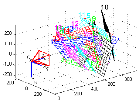
In a 3D scan system, calibrate a camera means extract the position of the ground plane in the chosen reference and a serial of parameters, necessary to the following elaboration. These parameters are called intrinsics and they are:
- focal length (fo)
- image center (cc)
- radial distortion factor (k)
As told before, the goal of the camera calibration is to estimate the intrinsics parameters (focal length, image center and radial distortion factor) and to identify the position of the ground plane in the solidal reference with the camera.
Cameras calibration is a basic procedure to extract metric piece of information from 2D images. A camera is usually represented by the central projector model pinhole camera. This model is defined by two parameters:
- Intrinsic parameters (from three to five): they describe the camera independently from their position in the space.
- Extrinsic parameters (six): they describe camera position in the space, independently from their internal features.
This model must be conveniently correct to consider optical distortions introduced by camera lenses. The use of this kind of lenses, introduces a distortion which is necessary to balance before making a whatever calculation.
In literature there are several models to describe this kind of phenomenon. The model which has been studied and developed by Maestro 3D, estimates the lenses distortions in order to obtain a calibration which allows an excellent attention in the scanning process.
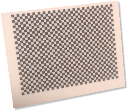
To calibrate a camera we could use the following way: focus on a chessboard whose dimensions are known, which is situated on the ground plane. From its examination, it is possible to obtain all the necessary piece of information.
[edit] How can I understand if my Scanner is not calibrated?
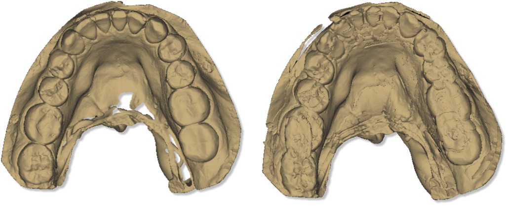
The main indicators of a non calibrated Scanner are clear disalignments on the surface, in the scanning process result.
In case of a bad calibration of the Scanner, it could be possible to see an error message of this type The object has moved during the Scanning process.
The picture here below, shows the same object, on the left we have a scan with a Scanner perfectly calibrated, while on the right a scan with a Scanner non-calibrated.
[edit] How many times it is necessary to calibrate the Scanner?
The quality of the materials and the solidity of the structure permit not to calibrate very often the Scanner if it has used correctly.
Nevertheless, excessive jump in the temperature or bad hits, could damage the machine and make the calibration necessary.
Small disalignments and imperfect calibrations are not evident on the final result, for this reason it is recommended to make the Scanner calibration every six months.
[edit] Calibration module activation
In order to activate the calibration module it is necessary to request and to load the license file.
For the calibration module request, it is necessary to communicate the serial number that appears, by tapping into the menu ![]() Help and by selecting
Help and by selecting ![]() About.
About.
After having received the license "eds.calibration.license", it will be necessary to charge it by tapping into the menu ![]() File and by selecting
File and by selecting ![]() Activate calibration module, choose the folder where there is the license file and tap twice on it.
Activate calibration module, choose the folder where there is the license file and tap twice on it.
[edit] Calibration kit
Calibration kit is composed by two objects:
- A calibration kit for cameras, composed by a small glass rectified plate, where a "chessboard" print in high definition has been pasted.
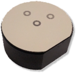
- a target for the rotary table calibration, that is a white adhesive disk with three black rings to put on the arch holder.
[edit] Main Toolbar
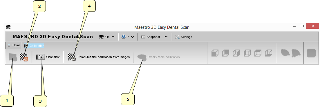
The main toolbar allows to access to every feature of Easy Dental Scan calibration module.
- 1) Connect
- 2) Disconnect
- 3) Snapshot
- 4) Compute the calibration from acquired images
- 5) Rotary table calibration
[edit] Camera Calibration - step by step
Calibration camera procedure consists in the acquisition of some images, where each of them films the calibration target in a different position one from the other.
To enter into the calibration module, tap on ![]() Calibration, from the main screen of Easy Dental Scan.
Calibration, from the main screen of Easy Dental Scan.
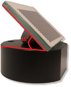
Before starting to the real calibration process, put into the scanner the arch holder plate with the calibration target on it. In order to obtain a "good" calibration it is necessary to place the target with an angle of about 45° respect to the plate, with some plastiline as support, as shown in the picture below.
By tapping on the button ![]() Connect on the calibration module toolbar, the software will proceed to the initialization of the variours components of the Scanner and on the monitor two windows will appear, one for the left camera (LX) and one for the right camera (RX). Moreover, on the software toolbar the buttons
Connect on the calibration module toolbar, the software will proceed to the initialization of the variours components of the Scanner and on the monitor two windows will appear, one for the left camera (LX) and one for the right camera (RX). Moreover, on the software toolbar the buttons ![]() Disconnect and
Disconnect and ![]() Snapshot will enable.
Snapshot will enable.
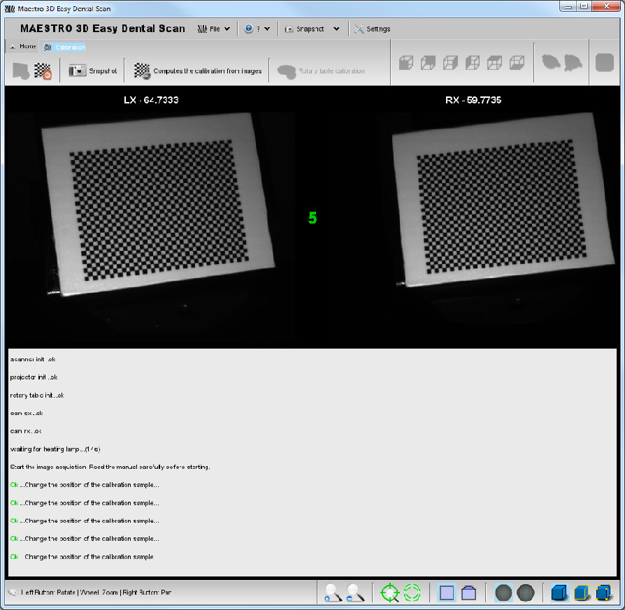
In order to reach a good result on the tool calibration, it will be necessary to acquire at least five images (ten recommended) from the calibration target. This is a very important phase and it is necessary to pay attention to the following instructions:
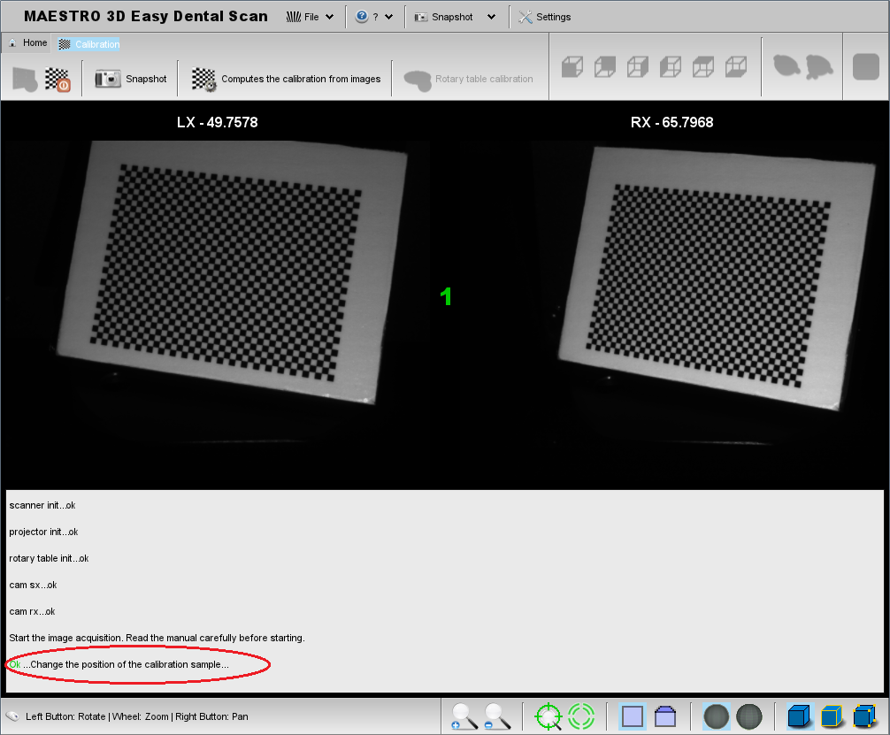
- Before every snapshot, check that every square of the chessboard of the calibration target are lighted up and visible both in the left camera (LX) and in the right one (RX).
The following picture shows the target correctly placed and acquired from the cameras.
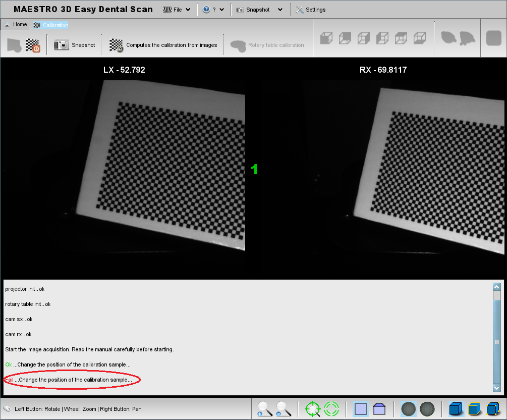
The following picture, on the contrary, shows the target placed in part out of the cameras field of vision and, at the bottom, the message of error in the acquisition.
- The calibration target must be placed in a different position between an acquisition (Snapshot) and another one.
- On the target there mustn't be any blots or scratches which could avoid the correct identification of every square.
- The calibration target must be absolutely fixed at the moment of acquisition.
- Once that the target has been placed on the plate, pay attention that there are not reflections on the surface. These reflections could be caused from the brighted source, in this case it will need to move the calibration target, or from the environmental light, in this case it is recommended to make the acquisition with the Scanner door closed.
- In order to avoid that jump in the temperature could frustrate the correct Scanner calibration, it is recommended to make the calibration process on the same temperature conditions into the ones that the machine will be used.
For the correct calibration target acquisition, follow this procedure:
- Put the calibration target on the scan holder in a position very close to the brighted source, then close the Scanner door and tap on the button
 Snapshot. The Software will provide to the object acquisition and, if the process has a successfull conclusion, in the monitor centre a green progressive number and at the bottom the message ok will appear. If the acquisition process has not a successfull conclusion, the progressive number will not grow up and, at the bottom of the monitor, a red message Failed will appear.
- Repeat the previous process, but this time by placing the target in the scan holder centre, then tap on the button
 Snapshot, and wait that the Software acquires the image and the green progressive number grows up of a unit.
- Change position to the target and place it to the farther point from the brighted source, then tap on the button
 Snapshot and wait the confirm of the made acquisition.
- Place the target to the extreme right and left respect to the brighted source and make the images acquisition with the button
 Snapshot.
The described procedure guarantees that the all cameras cover area is used. Nevertheless, it is recommended to repeat the acquisition operations for other five times, for ten snapshot in total, by paying attention to change the target position every time.
When at least five images have been acquired, on the calibration module toolbar the button ![]() Compute calibration from acquired images will be enabled. By tapping on it, the Software disables all the toolbar buttons, disconnectes the peripherals and proceeds to elaborate acquired data. If this procedure has a successfull conclusion, a window with the message
Compute calibration from acquired images will be enabled. By tapping on it, the Software disables all the toolbar buttons, disconnectes the peripherals and proceeds to elaborate acquired data. If this procedure has a successfull conclusion, a window with the message ![]() The calibration is finished with success and it has been installed will appear. The calibration file camera.calibration.xml is automatically saved in Easy Dental Scan.
The calibration is finished with success and it has been installed will appear. The calibration file camera.calibration.xml is automatically saved in Easy Dental Scan.
By tapping on the button OK the Software will come back to the calibration module main menu.
|
Important:
|
[edit] Rotary table calibration - step by step
Before making the rotary table calibration process, it is necessary to put the target on the arch holder plate, as shown in the picture.
To access to the rotary table calibration process, tap on the button ![]() Rotary table calibration, on the toolbar in the main screen of the calibration module.
Rotary table calibration, on the toolbar in the main screen of the calibration module.
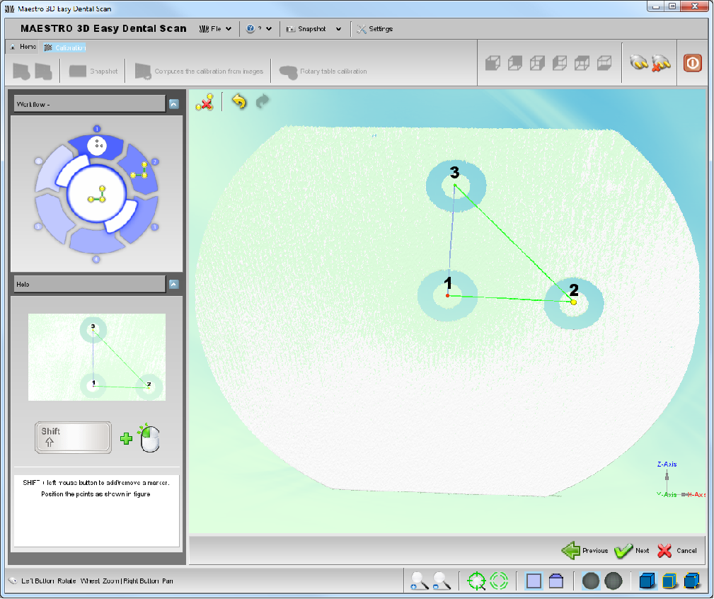
Place the rotary table calibration target as shown in the picture on the left, then tap on the button ![]() Next at the bottom, on the right.
Next at the bottom, on the right.
The scanner will make a target scanning and the Software will show the result after few seconds on the following screen.
By tapping on the SHIFT button on the keyboard, mark the centre of the black rings with a double click of the left button of the mouse, in the suggested order of the picture on the left.
Some modifications regarding the position or the points order could be done with the button ![]() Clean oppure
Clean oppure ![]() Cancel.
Cancel.
After having marked the centre of the three rings, the button ![]() Next at the bottom, on the right, will enable; by tapping on it the Software will proceed to install the file rotary.table.calibration.xml in Easy Dental Scan.
Next at the bottom, on the right, will enable; by tapping on it the Software will proceed to install the file rotary.table.calibration.xml in Easy Dental Scan.
