Maestro 3D Dental Scanner - Calibration
(→Toolbar Principale) |
(→Calibrazione delle telecamere - step by step) |
||
| Line 111: | Line 111: | ||
</div> | </div> | ||
| − | == | + | == Camera Calibration - step by step == |
<div align="justify"> | <div align="justify"> | ||
| − | + | Calibration camera procedure consists in the acquisition of some images, where each of them films the calibration proof in a different position one from the other. | |
| − | + | To enter into the calibration module, tap on [[image:Eds.calibration.png]] ''Calibration'', from the main screen of Easy Dental Scan. | |
| − | + | Before starting to the real calibration process, put into the scanner the arch holder plate with the calibration proof on it. | |
| − | + | In order to obtain a "good" calibration it is necessary to place the proof with an angle of about 45° respect to the plate, with some plastiline as support, as shown in the picture below. | |
| Line 127: | Line 127: | ||
| − | + | By tapping on the button [[image:Eds.CalibrationStart.png]] ''Connection'' on the calibration module toolbar, the software will proceed to the initialization of the variours components of the Scanner and on the monitor two windows will appear, one for the left camera (LX) and one for the right camera (RX). Moreover, on the software toolbar the buttons [[image:Eds.Calibration exit.png]] ''Disconnection'' and [[image:Eds.Snap.png]] ''Snapshot'' will enable. | |
| + | |||
| − | + | In order to reach a good result on the tool calibration, it will be necessary to acquire at least five images (ten recommended) from the calibration proof. This is a very important phase and it is necessary to pay attention to the following instructions: | |
| + | * Before every snapshot, check that every square of the chessboard of the calibration proof are lighted up and visible both in the left camera (LX) and in the right one (RX). | ||
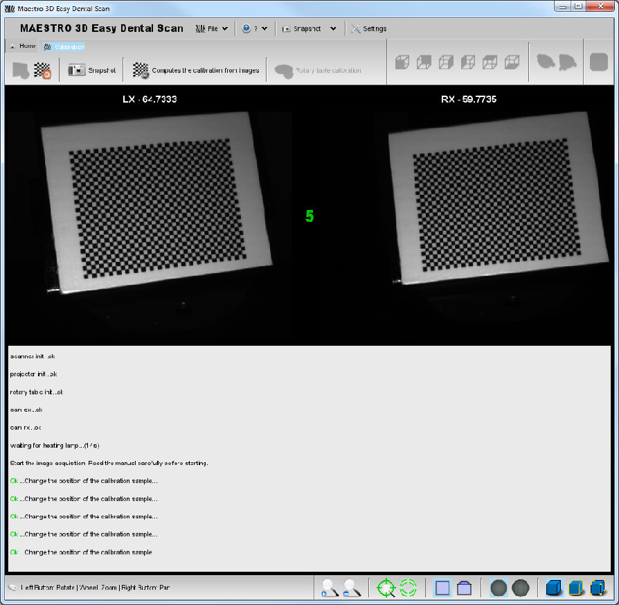
| − | + | The following picture shows the proof correctly placed and acquired from the cameras. | |
| − | |||
| Line 141: | Line 142: | ||
| − | + | The following picture, on the contrary, shows the proof placed in part out of the cameras field of vision and, at the bottom, the message of error in the acquisition. | |
| Line 148: | Line 149: | ||
| − | * | + | * The calibration proof must be placed in a different position between an acquisition (''Snapshot'') and another one. |
| + | |||
| + | * On the proof there must not be any blots or scratches which could avoid the correct identification of every square. | ||
| + | |||
| + | * The calibration proof must be absolutely fixed at the moment of acquisition. | ||
| − | * | + | * Once that the proof has been placed on the plate, pay attention that there are not reflections on the surface. These reflections could be caused from the brighted source, in this case it will need to move the calibration proof, or from the environmental light, in this case it is recommended to make the acquisition with the Scanner door closed. |
| − | + | ||
| − | + | ||
| − | + | ||
| − | + | ||
| − | + | ||
| − | + | ||
| + | * In order to avoid that jump in the temperature could frustrate the correct Scanner calibration, it is recommended to make the calibration process on the same temperature conditions into the ones that the machine will be used. | ||
Per la corretta acquisizione del provino di calibrazione procedere come segue: | Per la corretta acquisizione del provino di calibrazione procedere come segue: | ||
Revision as of 17:57, 4 December 2013
Contents |
What is calibration?
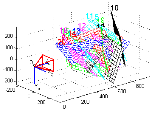
In a 3D scan system, calibrate a camera means extract the position of the ground plane in the chosen reference and a serial of parameters, necessary to the following elaboration. These parameters are called intrinsics and they are:
- focal length (fo)
- image center (cc)
- radial distortion factor (k)
As told before, the goal of the camera calibration is to estimate the intrinsics parameters (focal length, image center and radial distortion factor) and to identify the position of the ground plane in the solidal reference with the camera.
Cameras calibration is a basic procedure to extract metric piece of information from 2D images. A camera is usually represented by the central projector model pinhole camera. This model is defined by two parameters:
- Intrinsic parameters (from three to five): they describe the camera independently from their position in the space.
- Extrinsic parameters (six): they describe camera position in the space, independently from their internal features.
This model must be conveniently correct to consider optical distortions introduced by camera lenses. The use of this kind of lenses, introduces a distortion which is necessary to balance before making a whatever calculation.
In literature there are several models to describe this kind of phenomenon. The model which has been studied and developed by Maestro 3D, estimates the lenses distortions in order to obtain a calibration which allows an excellent attention in the scanning process.
To calibrate a camera we could use the following way: focus on a chessboard whose dimensions are known, which is situated on the ground plane. From its examination, it is possible to obtain all the necessary piece of information.
How can I understand if my Scanner is not calibrated?
The main indicators of a non calibrated Scanner are clear disalignments on the surface, in the scanning process result.
In case of a bad calibration of the Scanner, it could be possible to see an error message of this type The object has moved during the Scanning process.
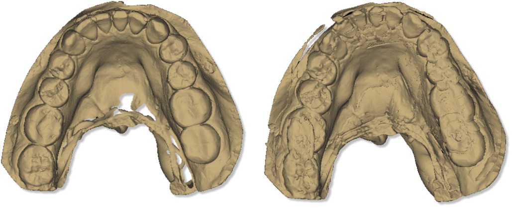
The picture here below, shows the same object, on the left we have a scan with a Scanner perfectly calibrated, while on the right a scan with a Scanner non-calibrated.
How many times it is necessary to calibrate the Scanner?
The quality of the materials and the solidity of the structure permit not to calibrate very often the Scanner if it has used correctly.
Nevertheless, excessive jump in the temperature or bad hits, could damage the machine and make the calibration necessary.
Small disalignments and imperfect calibrations are not evident on the final result, for this reason it is recommended to make the Scanner calibration every six months.
Calibration module activation
In order to activate the calibration module it is necessary to request and to load the license file.
For the calibration module request, it is necessary to communicate the serial number that appears, by login into the menu ![]() Help and by selecting
Help and by selecting ![]() About.
About.
After having received the license "eds.calibration.license", it will be necessary to charge it by login into the menu ![]() File and by selecting
File and by selecting ![]() Activate calibration module, choose the folder where there is the license file and tap twice on it.
Activate calibration module, choose the folder where there is the license file and tap twice on it.
Calibration kit
Calibration kit is composed by two objects:
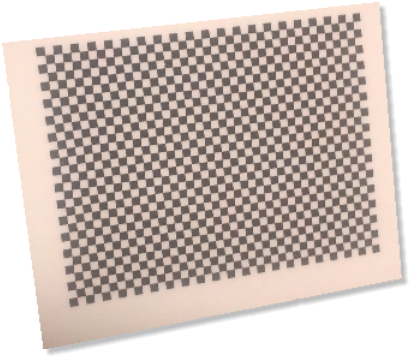
- A calibration proof for cameras, composed by a small glass rectified plate, where a "chessboard" print in high definition has been pasted.
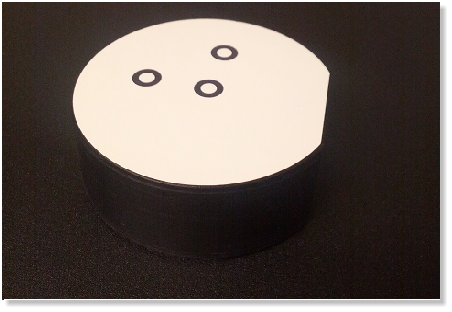
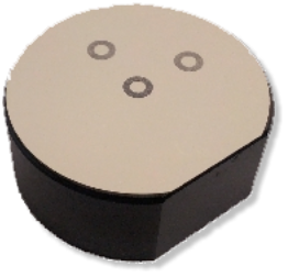
- a proof for the rotary table calibration, that is a white adhesive disk with three black rings to put on the arch holder.
Main Toolbar
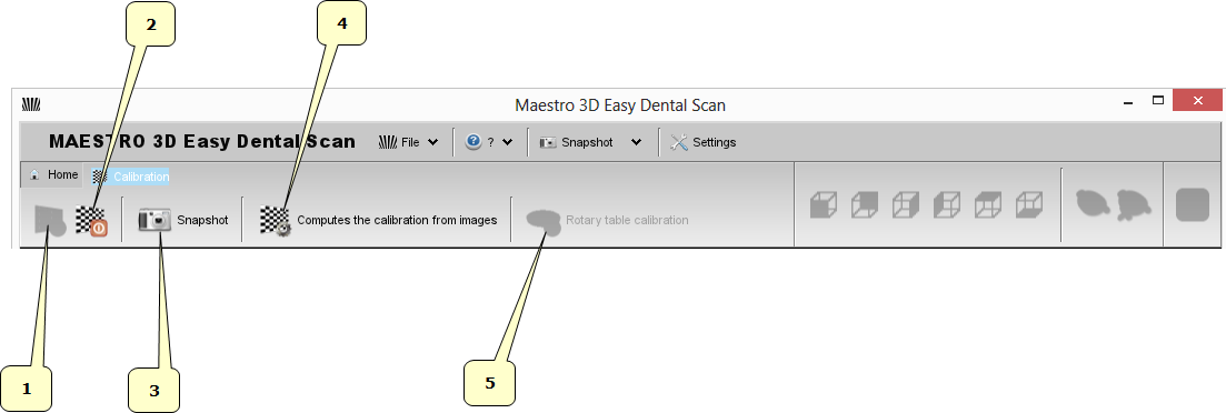
The main toolbar allows to access to every feature of Easy Dental Scan calibration module.
- 1) Connection
- 2) Disconnection
- 3) Snapshot
- 4) Compute the calibration from acquired images
- 5) Rotary table calibration
Camera Calibration - step by step
Calibration camera procedure consists in the acquisition of some images, where each of them films the calibration proof in a different position one from the other.
To enter into the calibration module, tap on ![]() Calibration, from the main screen of Easy Dental Scan.
Calibration, from the main screen of Easy Dental Scan.
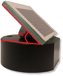
Before starting to the real calibration process, put into the scanner the arch holder plate with the calibration proof on it. In order to obtain a "good" calibration it is necessary to place the proof with an angle of about 45° respect to the plate, with some plastiline as support, as shown in the picture below.
By tapping on the button ![]() Connection on the calibration module toolbar, the software will proceed to the initialization of the variours components of the Scanner and on the monitor two windows will appear, one for the left camera (LX) and one for the right camera (RX). Moreover, on the software toolbar the buttons
Connection on the calibration module toolbar, the software will proceed to the initialization of the variours components of the Scanner and on the monitor two windows will appear, one for the left camera (LX) and one for the right camera (RX). Moreover, on the software toolbar the buttons ![]() Disconnection and
Disconnection and ![]() Snapshot will enable.
Snapshot will enable.
In order to reach a good result on the tool calibration, it will be necessary to acquire at least five images (ten recommended) from the calibration proof. This is a very important phase and it is necessary to pay attention to the following instructions:
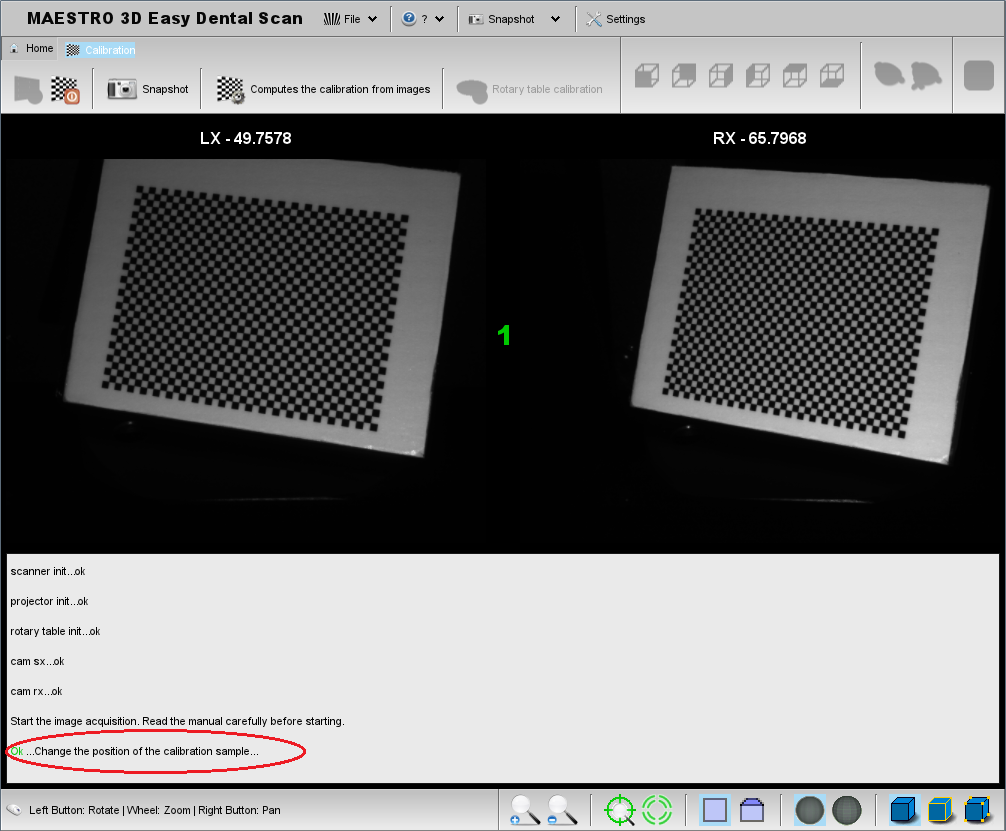
- Before every snapshot, check that every square of the chessboard of the calibration proof are lighted up and visible both in the left camera (LX) and in the right one (RX).
The following picture shows the proof correctly placed and acquired from the cameras.
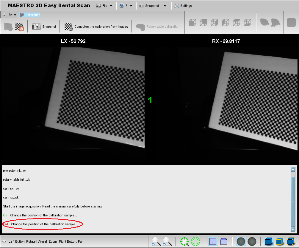
The following picture, on the contrary, shows the proof placed in part out of the cameras field of vision and, at the bottom, the message of error in the acquisition.
- The calibration proof must be placed in a different position between an acquisition (Snapshot) and another one.
- On the proof there must not be any blots or scratches which could avoid the correct identification of every square.
- The calibration proof must be absolutely fixed at the moment of acquisition.
- Once that the proof has been placed on the plate, pay attention that there are not reflections on the surface. These reflections could be caused from the brighted source, in this case it will need to move the calibration proof, or from the environmental light, in this case it is recommended to make the acquisition with the Scanner door closed.
- In order to avoid that jump in the temperature could frustrate the correct Scanner calibration, it is recommended to make the calibration process on the same temperature conditions into the ones that the machine will be used.
Per la corretta acquisizione del provino di calibrazione procedere come segue:
- Posizionare il provino di calibrazione sul piattino porta arcata dello scanner nella posizione più vicina alla sorgente luminosa, chiudere lo sportello dello scanner e premere il pulsante
 Snapshot. Il software provvederà all'acquisizione dell'oggetto e se tale processo andrà a buon fine, nel centro dello schermo apparirà un numero progressivo in verde e in basso il messaggio ok. Qual'ora l'acquisizione non andasse a buon fine, il progressivo non aumenterà e in basso nello schermo apparirà il messaggio di errore Fallito in rosso.
- Ripetere la precedente operazione questa volta posizionando il provino nel centro del piattino porta arcata, premere il pulsante
 Snapshot, e attendere che il software acquisisca l'immagine e il progressivo verde aumenti di una unità.
- Cambiare posizione al provino e posizionarlo nel punto più distante dalla sorgente luminosa, premere il pulsante
 Snapshot e attendere la conferma dell'avvenuta acquisizione.
- Procedere allo spostamento del provino nella posizione di estrema destra e sinistra rispetto alla sorgente luminosa ed effettuare l'acquisizione delle immagini con il pulsante
 Snapshot.
La procedura descritta garantisce che l'intera area di copertura delle telecamere venga utilizzata. Si consiglia tuttavia di ripetere le operazioni di acquisizione per altre cinque volte, per un totale di 10 snapshot, facendo attenzione a cambiare ogni volta la posizione del provino.
Dopo aver acquisito con successo almeno cinque immagini, sulla barra degli strumenti del modulo di calibrazione si abiliterà il pulsante ![]() Calcolare la calibrazione dalle immagini acquisite. Premendolo il software disabilita tutti i pulsanti sulla barra degli strumenti, disconnette le periferiche e procede ad elaborare i dati acquisiti. Se la procedura va a buon fine apparirà una finestra con il messaggio
Calcolare la calibrazione dalle immagini acquisite. Premendolo il software disabilita tutti i pulsanti sulla barra degli strumenti, disconnette le periferiche e procede ad elaborare i dati acquisiti. Se la procedura va a buon fine apparirà una finestra con il messaggio ![]() La calibrazione è terminata con successo ed è stata installata. Il file di calibrazione camera.calibration.xml viene automaticamente salvato in Easy Dental Scan.
La calibrazione è terminata con successo ed è stata installata. Il file di calibrazione camera.calibration.xml viene automaticamente salvato in Easy Dental Scan.
Premendo il pulsante OK il software tornerà alla schermata iniziale del modulo di calibrazione.
|
Importante:
|
Calibrazione della tavola rotante - step by step
Prima di effettuare la procedura di calibrazione della tavola rotante, applicare sul piattino porta arcata il provino come mostrato in figura.
Per accedere alla procedura di calibrazione della tavola rotante cliccare sul pulsante ![]() Calibrazione della tavola rotante posizionato sulla barra degli strumenti nella schermata iniziale del modulo di calibrazione.
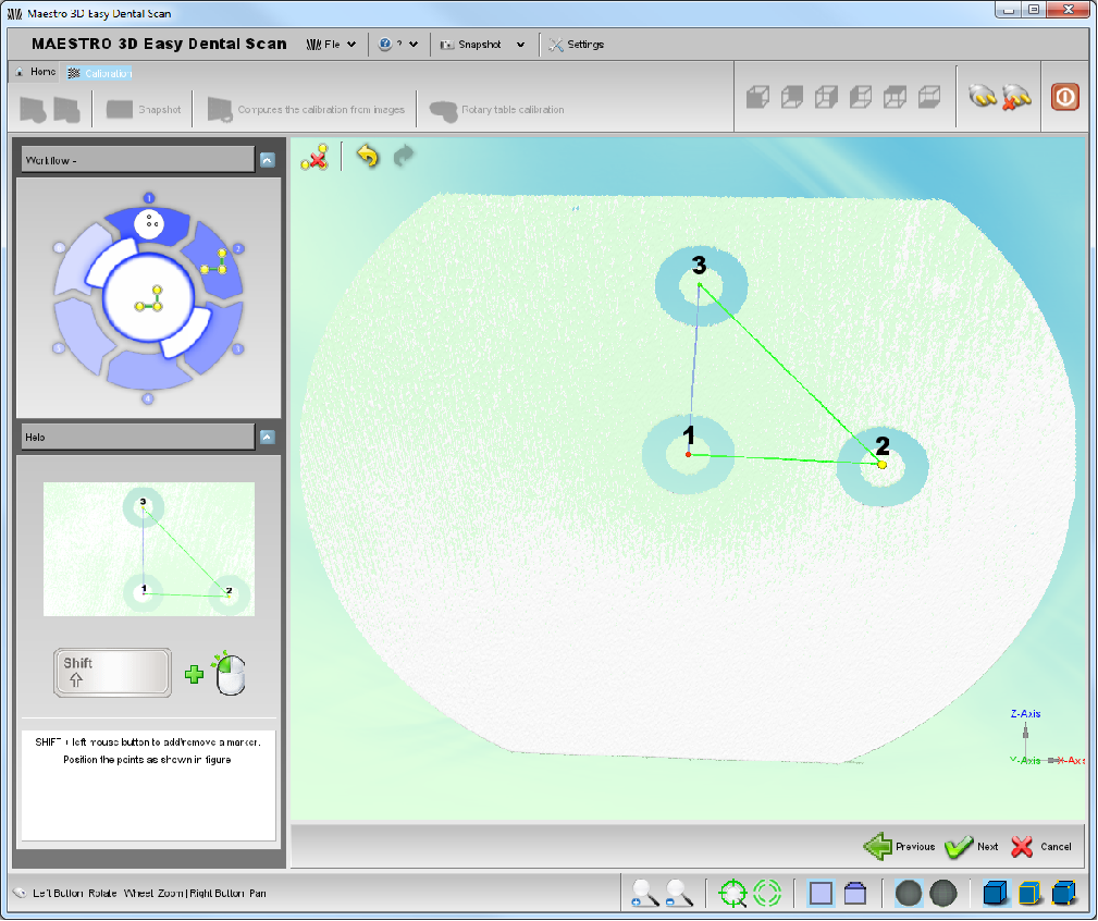
Posizionare il provino di calibrazione della tavola rotante come mostrato nella figura a sinistra nella schermata, quindi procedere cliccando il pulsante
Calibrazione della tavola rotante posizionato sulla barra degli strumenti nella schermata iniziale del modulo di calibrazione.
Posizionare il provino di calibrazione della tavola rotante come mostrato nella figura a sinistra nella schermata, quindi procedere cliccando il pulsante ![]() Avanti in basso a destra.
Avanti in basso a destra.
Lo scanner effettuerà una scansione del provino e il software mostrerà dopo pochi secondi il risultato nella schermata successiva.
Tenendo premuto il Tasto SHIFT sulla tastiera, procedere a marcare il centro degli anelli neri con un doppio click del tasto sinistro del mouse, nell'ordine suggerito nella figura a sinistra.
Eventuali modifiche nella posizione o nell'ordine dei punti possono essere effettuate con il pulsante ![]() Pulisci oppure
Pulisci oppure ![]() Annulla.
Annulla.
Dopo aver marcato il centro dei tre anelli si abiliterà in basso a destra il pulsante ![]() Avanti, premendolo il software procederà ad installare il file rotary.table.calibration.xml in Easy Dental Scan.
Avanti, premendolo il software procederà ad installare il file rotary.table.calibration.xml in Easy Dental Scan.
