Maestro 3D Easy Dental Scan - User Manual
Introduction to the use of Maestro 3D Easy Dental Scan software
The aim of this document is to introduce the user to the use of the Easy Dental Scan Software, in a simple and quick way. Please read this manual carefully before making use of the Easy Dental Scan Software. Maestro Easy Dental Scan is the software that combines with the line of Maestro 3D dental scanners. The software allows automatic acquisition of the dental objects with one click and creation of 3D surfaces of the acquired data entirely automatic, without any user intervention. The innovative software guarantees exceptional performances, fully exploiting the parallel calculation offered by the most recent multicore and multithreading technologies available on the market.
Installazione del Software
UAC - User Account Control
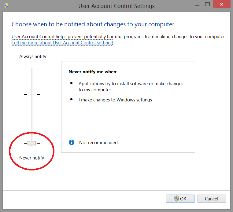
To avoid difficulties and limitations in the use of the Software, it is necessary to set the UAC slider - User Account Control to the minimum value as shown in the picture below.
To log in to the setting window: Control panel-> User Account-> Change Settings User Account Control.
Administrator's Rights
In order yo put in operation the Software it is necessary to set correctly administrator's rights.
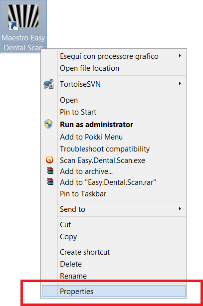
Follow the instructions as shown in the pictures below.
Right button of the mouse on the Software's icon to start the contextual menu and select the entry properties.
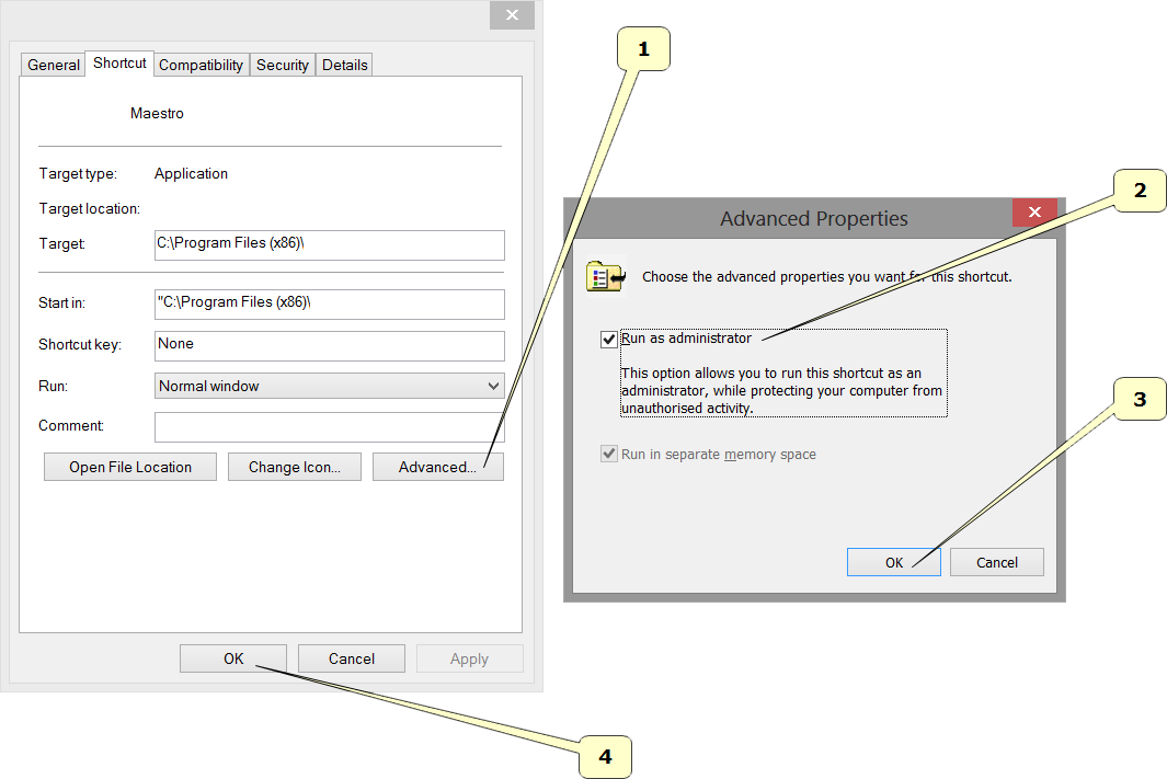
Follow the steps as shown in the sequency from 1 to 4.
- Press the button Advanced.
- Select the voice Run as administrator.
- Press the button Ok.
- Press the button Ok.
User Interface
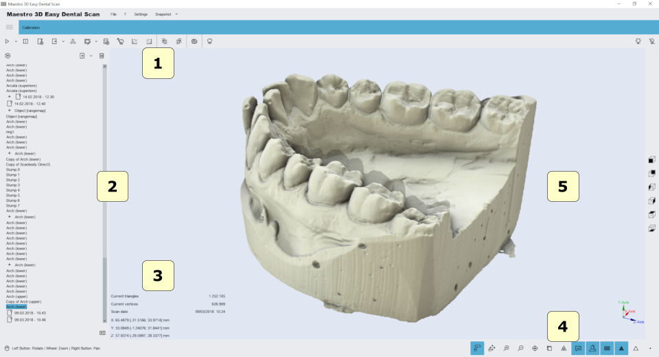
The figure below shows the composition of the user interface.
- 1) Main Toolbar.
- 2) Tree Area.
- 3) Info Area.
- 4) Bottom Area.
- 5) Visualization\Editing Area
Main Toolbar
The main toolbar allows the access to all functionalities of Easy Dental Scan Software.
- 1) New Acquisition - Start a new scan.
- 2) Scanner Status - Activates the window that monitors the hardware scanner status.
- 3) New Group - Adds a new group in the tree. It's possible to move the elements of the tree inside/outside a group by mouse drag and drop.
- 4) Export (Z Axis) - Export the selected item along the Z Axis. You can also select the option Export (Y Axis).
- 5) Postprocess (convert scanned data into a 3D model) - The function is enabled when an item is selected not postprocessed. This operation can take a few minutes to converts the scanned data from the scanner in a triangular geometry.
- 6) Edit - Edit the selected items. This is useful for removing artifacts due to scanning, to remove the putty scanned, for make the holefilling, the decimation, 2D\3D selection edit, etc.
- 7) Import a scanbody from library.
- 8) Align dies on arch - automatic alignment procedure of the stumps.
- 9)
- Manual align 3-2-1 - Set Fixed item - Set the selected item as fixed in the manual align procedure.
- Manual align 3-2-1 - Set Floating item - Set the selected item as floating in the manual align procedure.
- 10) Measures - free measures:
- point-point measures.
- angle measures.
- 11) CAD - send selected items to the CAD software.
- 12) Views:
- front view.
- rear view.
- right side view.
- left side view.
- top view.
- bottom view.
- 13) Projector status.
- Power on.
- Power off.
- 14) Exit.
Bottom Toolbar
The bottom toolbar is the area of the screen containing a progress bar that is displayed and updated during each computation of the program and the controls for changing the visual settings of the visualization/editing area.
- 1) magnify in [Key PGDown]/magnify out [Key PGUp].
- 2) show/hide trackball.
- 3) reset trackball [Key R].
- 4) parallel projection [Key O], perspective projection [Key P].
- 5) smooth shading [Key S], flat shading [Key F].
- 6) show/hide triangles, edges [Key E], vertices [Key V].
Visualization / Editing Area and Info Area
The visualization / editing area is the area of the window in which the models are visualized and all the editing operations are performed.
In the visualization area it is possible to see the models and edit and measure distance between different point.
In order to examine the models displayed in the visualization / editing area camera parameters (position, scale and rotation) can be setted using an instrument called trackball.
The trackball is very simple to use. Just use the Left mouse button dragging to rotate around the model, the mouse wheel to Zoom in / Zoom out and the Right mouse dragging to move (pan) the camera.
The info area of the screen shows the info related to the current item.
Tree Area
The Tree Area contains all the models scanned. The Tree Area organization has a tree. The use of groups allows you to keep an ordering of the models scanned. To select a model from the Tree Area just click on it with the left mouse button. The models selected will be displayed on Visualization Area. To select more models click by holding down the CTRL\SHIFT key.
The Tree Area can contain the following elements:
| |
Stump |
| |
Upper Jaw |
| |
Lower Jaw |
| |
Upper\Lower Gingiva |
| |
Upper\Lower Waxup |
| |
Maxillary\Mandibular Relationship |
| |
Rangemap |
| |
Group |
For each of these elements there is associated a set of operations accessible via enabled icons in the Main Toolbar. These allow the user to access the main functions of the software.
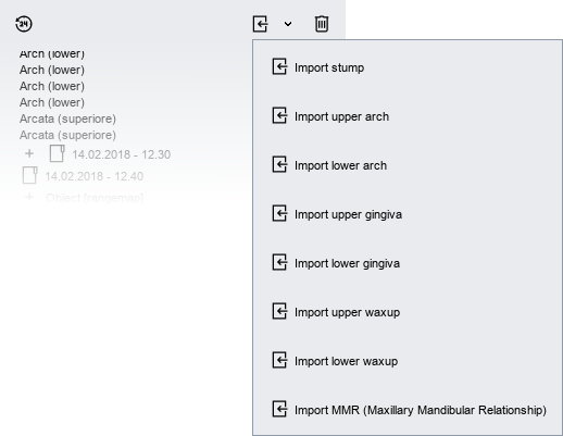
By accessing the drop-down menu as shown in the following figure, you can import into the tree the STL file.
Scan parameters
To start a new acquisition just press ![]() New acquisition in the Main Toolbar.
New acquisition in the Main Toolbar.
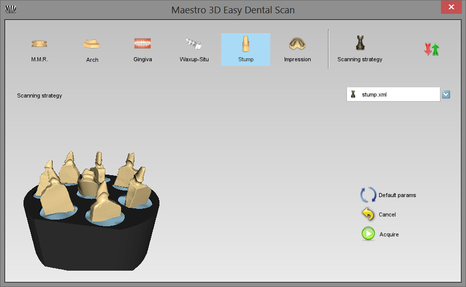
Through this window you can choose the type of object to be scanned
Cliccando su ![]() Opzioni Avanzate si apre la seguente finestra nella quale si possono andare a modificare i parametri di scansione.
Opzioni Avanzate si apre la seguente finestra nella quale si possono andare a modificare i parametri di scansione.
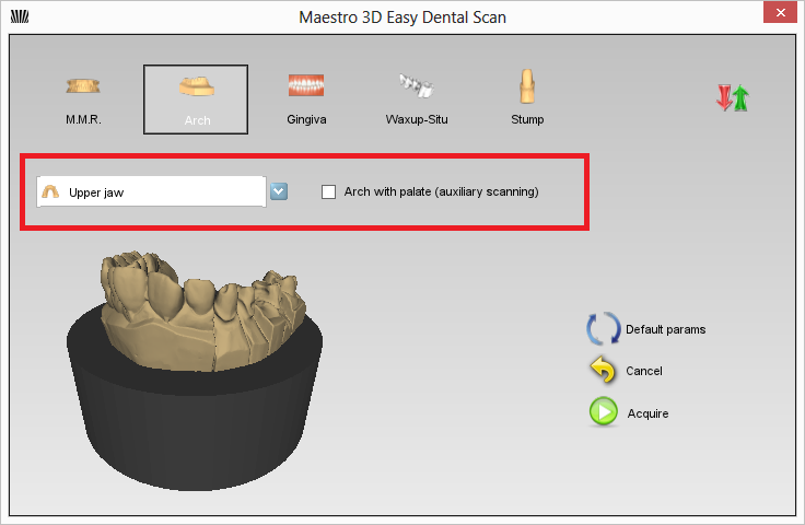
Nel caso si scelga di scansionare un'arcata, gengiva o waxup, sarà possibile selezionare se si tratta di elemento superiore o inferiore ed effettuare se necessario, la scansione ausiliaria del palato.
Toolbar dei Modelli
Area delle Impostazioni
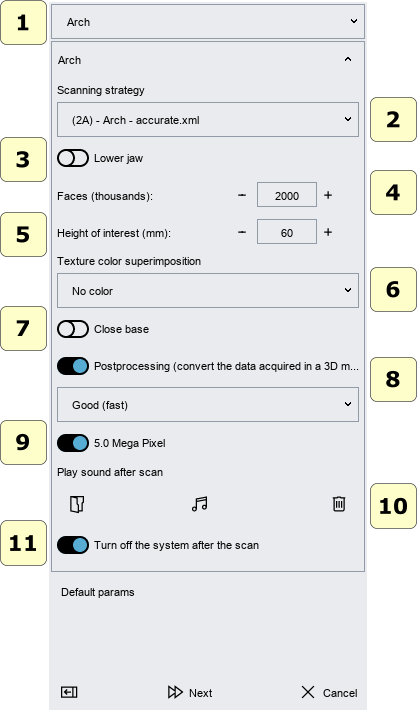
In questa parte della finestra si possono definire i parametri della scansione.
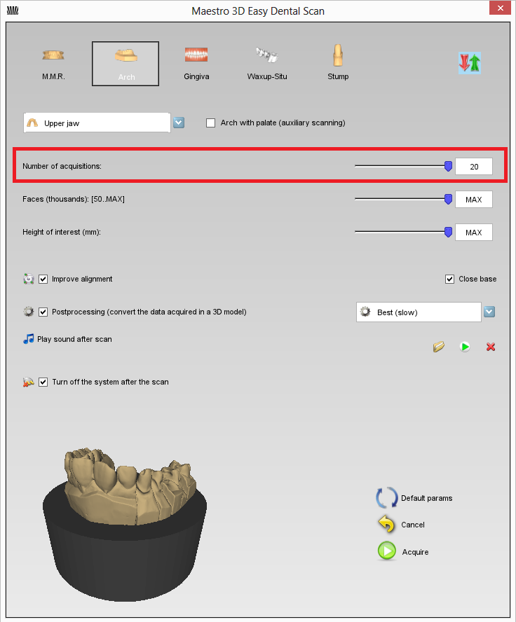
- Numero di acquisizioni:
Questo numero definisce il numero di riprese che verranno fatte sul modello considerando che questo farà un giro completo di 360 gradi sulla tavola rotante. Ad esempio se si sceglie 4 acquisizioni, il modello ruoterà sulla tavola rotante di 90 gradi dopo ogni acquisizione.
Un numero maggiore di acquisizioni comporta un tempo maggiore per completare la scansione ma consente di acquisire un maggior numero di punti.
|
ATTENZIONE Potrebbe accadere che con un numero basso di acquisizioni (es. 4-5) per determinati modelli possa fallire la scansione perché non c'è sufficiente sovrapposizione di geometria fra le varie riprese. In questo caso è sufficiente aumentare il numero di acquisizioni. |
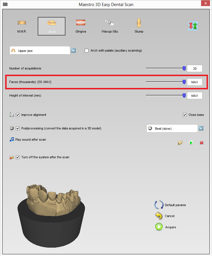
- Facce (triangoli):
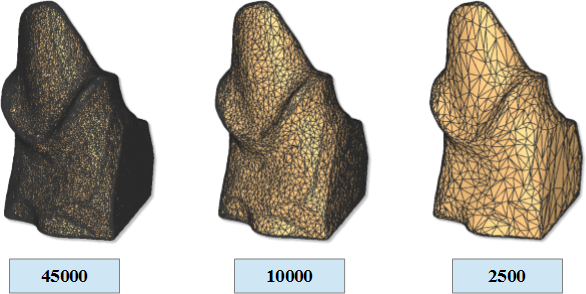
Questo numero definisce il numero di triangoli desiderati per il modello finale. La figura sottostante mostra lo stesso modello con 45000, 10000 e 2500 triangoli. La precisione e l'accuratezza dei 3 modelli e' equivalente.
Il sistema acquisisce sempre alla massima precisione e massima accuratezza ottenendo un modello al massimo numero di triangoli. Dopo questo viene decimato per ottenere il numero di triangoli desiderati. E' anche possibile decimare in un secondo momento tramite l'apposita' funzionalita' di decimazione.
|
ATTENZIONE Maggiore e' il numero di triangoli, maggiori saranno le dimensioni in byte del file STL.
|
Buttons Area
Processo di Scansione
Relazione Mascellare e Mandibolare
Arcata
Gengiva
Waxup - Situazione Presistente
Monconi
Filtri di Editing
Taglio con selezione rettangolare 2D
Taglio con selezione libera 3D
Taglio con selezione libera 2D
