Maestro 3D Easy Dental Scan - User Manual
Introduction to the use of Maestro 3D Easy Dental Scan software
The aim of this document is to introduce the user to the use of the Easy Dental Scan Software, in a simple and quick way. Please read this manual carefully before making use of the Easy Dental Scan Software. Maestro Easy Dental Scan is the software that combines with the line of Maestro 3D dental scanners. The software allows automatic acquisition of the dental objects with one click and creation of 3D surfaces of the acquired data entirely automatic, without any user intervention. The innovative software guarantees exceptional performances, fully exploiting the parallel calculation offered by the most recent multicore and multithreading technologies available on the market.
Installazione del Software
UAC - User Account Control
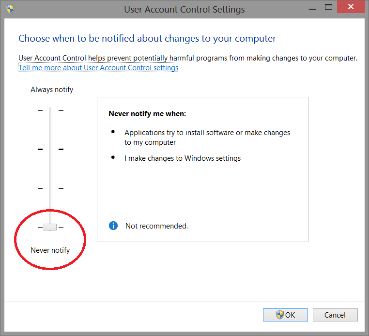
To avoid difficulties and limitations in the use of the Software, it is necessary to set the UAC slider - User Account Control to the minimum value as shown in the picture below.
To log in to the setting window: Control panel-> User Account-> Change Settings User Account Control.
Administrator's Rights
In order yo put in operation the Software it is necessary to set correctly administrator's rights.
Follow the instructions as shown in the pictures below.
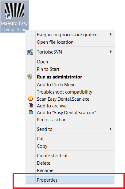
Right button of the mouse on the Software's icon to start the contextual menu and select the entry properties.
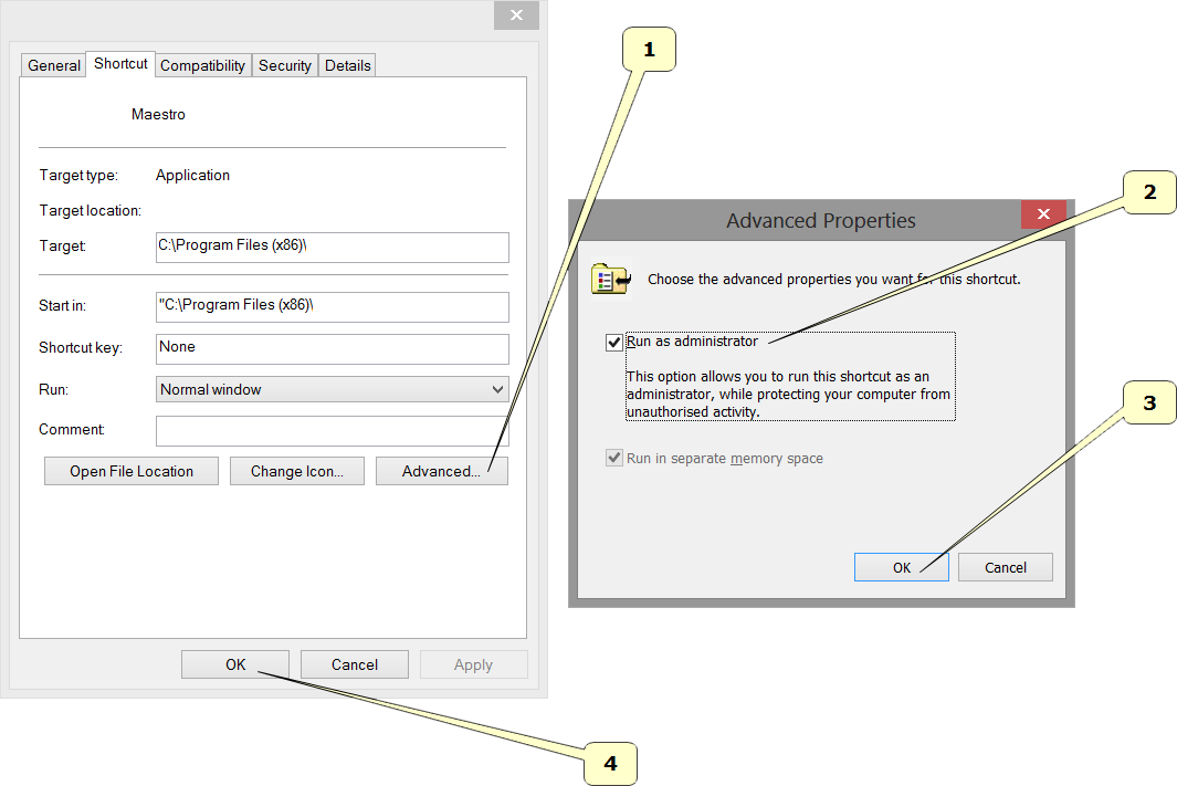
Follow the steps as shown in the sequency from 1 to 4.
- Press the button Advanced.
- Select the voice Run as administrator.
- Press the button Ok.
- Press the button Ok.
User Interface
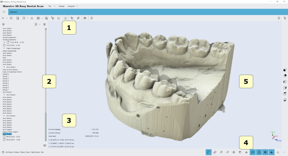
The figure below shows the composition of the user interface.
- 1) Main Toolbar.
- 2) Tree Area.
- 3) Info Area.
- 4) Bottom Area.
- 5) Visualization\Editing Area
Main Toolbar
The main toolbar allows the access to all functionalities of Easy Dental Scan Software.
- 1) New Acquisition - Start a new scan.
- 2) Scanner Status - Activates the window that monitors the hardware scanner status.
- 3) New Group - Adds a new group in the tree. It's possible to move the elements of the tree inside/outside a group by mouse drag and drop.
- 4) Export (Z Axis) - Export the selected item along the Z Axis. You can also select the option Export (Y Axis).
- 5) Postprocess (convert scanned data into a 3D model) - The function is enabled when an item is selected not postprocessed. This operation can take a few minutes to converts the scanned data from the scanner in a triangular geometry.
- 6) Edit - Edit the selected items. This is useful for removing artifacts due to scanning, to remove the putty scanned, for make the holefilling, the decimation, 2D\3D selection edit, etc.
- 7) Import a scanbody from library.
- 8) Align dies on arch - automatic alignment procedure of the stumps.
- 9)
- Manual align 3-2-1 - Set Fixed item - Set the selected item as fixed in the manual align procedure.
- Manual align 3-2-1 - Set Floating item - Set the selected item as floating in the manual align procedure.
- 10) Measures - free measures:
- point-point measures.
- angle measures.
- 11) CAD - send selected items to the CAD software.
- 12) Views:
- front view.
- rear view.
- right side view.
- left side view.
- top view.
- bottom view.
- 13) Projector status.
- Power on.
- Power off.
- 14) Exit.
Bottom Toolbar
The bottom toolbar is the area of the screen containing a progress bar that is displayed and updated during each computation of the program and the controls for changing the visual settings of the visualization/editing area.
- 1) magnify in [Key PGDown]/magnify out [Key PGUp].
- 2) show/hide trackball.
- 3) reset trackball [Key R].
- 4) parallel projection [Key O], perspective projection [Key P].
- 5) smooth shading [Key S], flat shading [Key F].
- 6) show/hide triangles, edges [Key E], vertices [Key V].
Visualization / Editing Area and Info Area
The visualization / editing area is the area of the window in which the models are visualized and all the editing operations are performed.
In the visualization area it is possible to see the models and edit and measure distance between different point.
In order to examine the models displayed in the visualization / editing area camera parameters (position, scale and rotation) can be setted using an instrument called trackball.
The trackball is very simple to use. Just use the Left mouse button dragging to rotate around the model, the mouse wheel to Zoom in / Zoom out and the Right mouse dragging to move (pan) the camera.
The info area of the screen shows the info related to the current item.
Tree Area
The Tree Area contains all the models scanned. The Tree Area organization has a tree. The use of groups allows you to keep an ordering of the models scanned. To select a model from the Tree Area just click on it with the left mouse button. The models selected will be displayed on Visualization Area. To select more models click by holding down the CTRL\SHIFT key.
The Tree Area can contain the following elements:
| |
Stump |
| |
Upper Jaw |
| |
Lower Jaw |
| |
Upper\Lower Gingiva |
| |
Upper\Lower Waxup |
| |
Maxillary\Mandibular Relationship |
| |
Rangemap |
| |
Group |
For each of these elements there is associated a set of operations accessible via enabled icons in the Main Toolbar. These allow the user to access the main functions of the software.
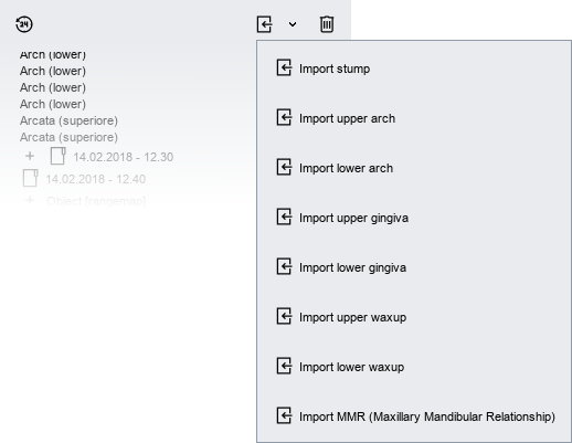
By accessing the drop-down menu as shown in the following figure, you can import into the tree the STL file.
Scan parameters
To start a new acquisition just press ![]() New acquisition in the Main Toolbar.
New acquisition in the Main Toolbar.
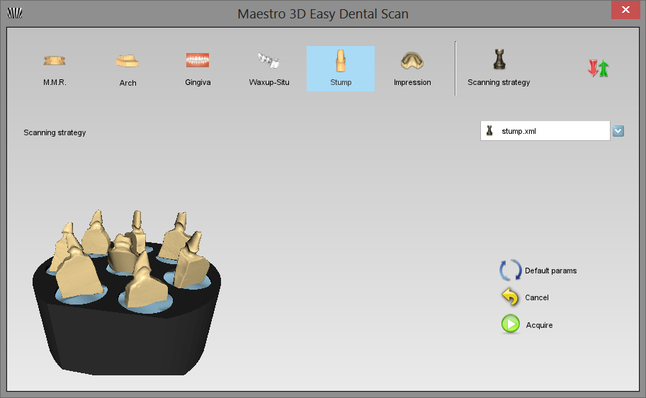
Through this window you can choose the type of object to be scanned
Just click ![]() Advanced Options to access to advanced options for scanning.
Advanced Options to access to advanced options for scanning.
If you choose to scan an arch, gum, waxup or impression, you can choose if it's an upper or lower element.
Advanced Options
In questa parte della finestra si possono definire i parametri della scansione.
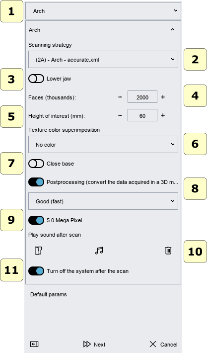
- Scanning Strategy:
It's possible to choose a scanning strategy. The strategies are available depending on whether the tilt module is activated or not. If you do not have the Tilt module active, all of the strategies shown only work with the rotary axis.
|
WARNING It may happen that with a low number of acquisitions (eg 4-5) for certain models may fail to scan because there is not sufficient overlap geometry between the various shots. In this case it is sufficient to increase the number of acquisitions into the strategy. |
- Faces (triangles):
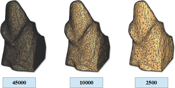
This number defines the number of triangles you want in your final model. The figure below shows the same model with 45000, 10000 and 2500 triangles. The precision and accuracy in the 3 models is equivalent. Among the 3 models changes the number of triangles that approximate the surface geometry. The system acquires always at max precision and max accurancy. Only after obtaining the final three-dimensional model at max number of triangles, it is decimated to obtain the desired number of triangles. Is also possible to decimate the model later.
|
WARNING Greater is the number of triangles, greater is the size of the STL file.
|
Recommended values:
| Arch\Gum\Waxup\Impression | 180000 - 300000 triangles |
| Stump | 15000 - 60000 triangles |
| MMR | 180000 - 300000 triangles |
- Height of interest:
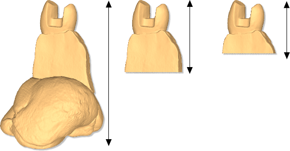
This param allows you to choose the height of interest of the model, (this height value is measured starting from top to bottom).
First picture (from left to right) shows the model of a stump where the height of interest parameter is disabled and then the stump is acquired entirely including the adhesive putty support that sustains it. Subsequent images display the same stump with the height of interest parameter set at 20 mm and 15 mm respectively (as can be seen the adhesive putty support is automatically removed).
It is important to remember that, in order to make the best use of this parameter, the model (arc, one or more stumps, etc...) must be placed perpendicular to the surface of the rotary table.
|
IMPORTANT Cut the model choosing the height of interest reduces the computation time of postprocessing and can improve the quality of the results. (Especially a smaller volume of the point cloud of the stumps can lead to a better yield of the final model). |
In any case, you can always remove the not interesting geometry, at any time, by editing the model.
- Improve alignment:
If this option is checked, the software will use a procedure that will improve the alignment of the various acquisitions. This is not recommended if you use strategies with numerous acquisitions. This is because the time taken could be very high.
- Postprocessing (convert the data acquired in a 3D model):
If this option is checked, the system automatically postprocessing the data acquired and it builds the triangular geometry surface. If it is not checked the data will be not postprocessed. It is possible postprocess the data acquired later.
|
TIPS To reduce the time of interaction with the scanner, where you have many models to be scanned is advisable not to make the postprocessing after each scan. In this case it is recommended scan all model (not check the option "Postprocessing", no check the option "Turn off") and at the end of the work, turn off the system and select from the tree area all items (rangemaps) and press button to postprocess all models. |
- Turn off the system after the scan:
Turn off the system after the end of the scan.
|
TIPS Remember to turn the system off when not in use to avoid wasting the lamp. |
Scanning process
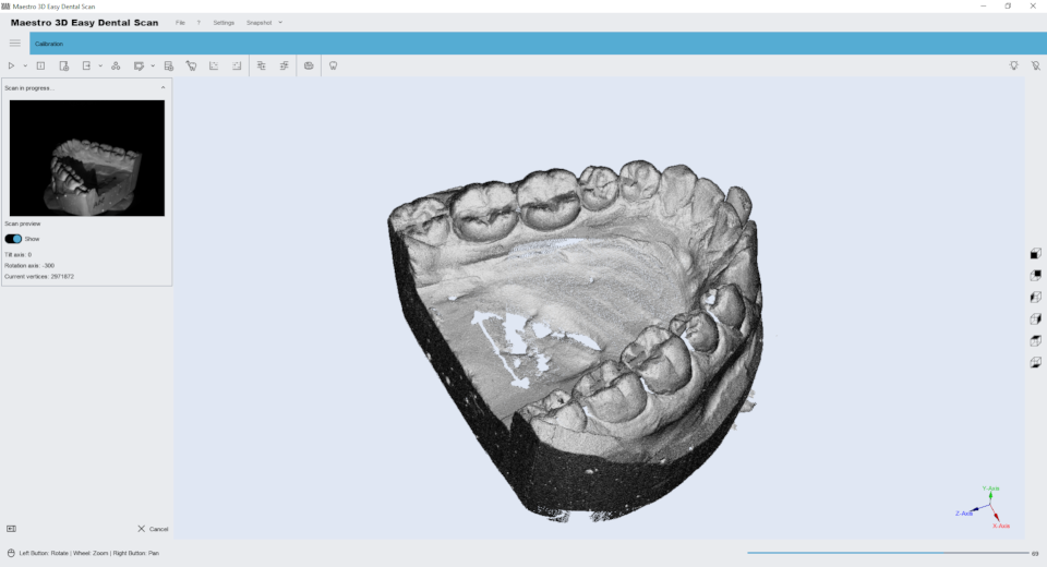
This window shows the progress of the scanning phase. This may take a few seconds or a few minutes depending on the strategy chosen.
In the window on the left shows the 2D image acquisition and 3D image on the right.
After this operation, if the the option "Postprocessing" was checked the software automatically generates the surface of the model from the acquired points, and adds to the Tree Area a new element. Then selecting it in the Tree Area, the model is displayed into the Visualization Area.
If the option "Postprocessing" was not checked, the software adds to the Tree Area a new element with a greyscale icon. Before you can perform any operation of this model is necessary to postprocess the data acquired.
Filtri di Editing
Taglio con selezione rettangolare 2D
Taglio con selezione libera 3D
Taglio con selezione libera 2D
