Maestro 3D Dental Studio V5 - User Manual
Contents |
Video Tutorials
Software Installation
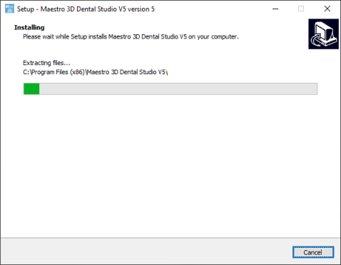
To install the software, run the installation file with administrator rights. In the various phases of the installation process, it will be possible to choose the destination folder, whether or not to add an icon to our desktop, etc. See the image below which shows an installation step.
This operation takes a few minutes.
At the end of the operation, the installation will have created two icons on the desktop ![]()
- Maestro 3D Dental Studio the CAD application;
- Maestro 3D Dental Studio Order Management the software for managing the customer database and creating a new case and opening an existing one.
Administrator rights
To execute the software correctly it is necessary to set the administrator rights correctly. Follow the instructions as shown in the pictures below. Right click on the software icon to activate the contextual menu and select the Open destination folder item.
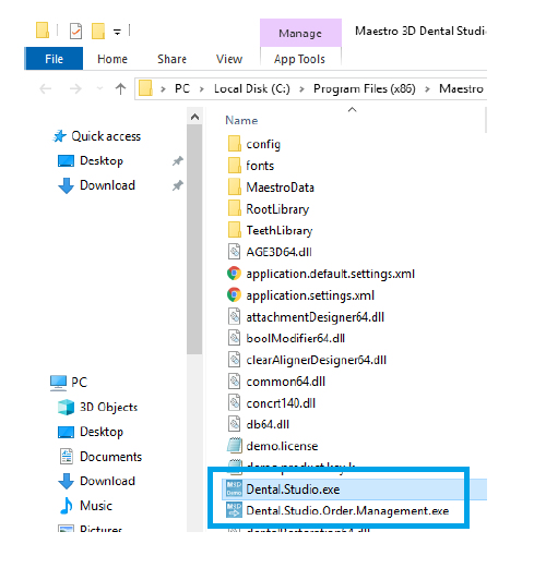
A window will appear showing the contents of the installation folder, as shown in the image below:
For both executables Dental.Studio.exe and Dental.Studio.Order.Management.exe, one at a time, right click to activate the contextual menu and select Properties.
As shown in the figure above, press the Compatibility tab and check the item Run this program as an administrator and press OK to confirm.
As a last thing, right click once again on the software icons on the desktop to activate the contextual menu and select the Properties item.
As shown in the figure below, press the Compatibility tab and check the item Run this program as an administrator and press OK to confirm.
First activation of the license
Before starting check:
- to have an internet connection;
- to have added to the exceptions list of your firewall and antivirus the executable software Dental.Studio.exe and Dental.Studio.Order.Management.exe.
At the first run the software will show a window like this:
- Product Key write the assigned and unique product code for your license;
- Mail write your email to receive confirmation of activation;
- Workstation name write the name you prefer for the workstation.
Press Next to activate the license.
Important notes on the license
The activation procedure, described above, activates the license on the workstation.
It is necessary to repeat the activation procedure each time the workstation is modified or changed. For this reason it is recommended to keep the product code.
The maximum number of workstations that can be activated is 3. However, the license cannot work simultaneously in more than one workstation.
The license, after the first activation, can work offline. The workstation may therefore not be connected to the Internet.
Only for the first activation it is necessary to use an Internet connection.
However, we recommend using the software on a workstation connected to the Internet to check for software updates.
Order Management
The Order Management application allows you to manage work cases.
- database management of clinics, doctors and patients and cases associated with patients;
- creating a new work case, importing files from disk or directly interfacing with the Maestro 3D scanner;
- opening of existing work cases.
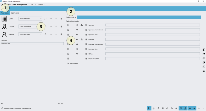
Create a new Orthodontic work case
- 1 New case tab;
- 2 Orthodontics tab;
- 3 Clinic, doctor and patient management;
- 4 Input file for an orthodontic case.
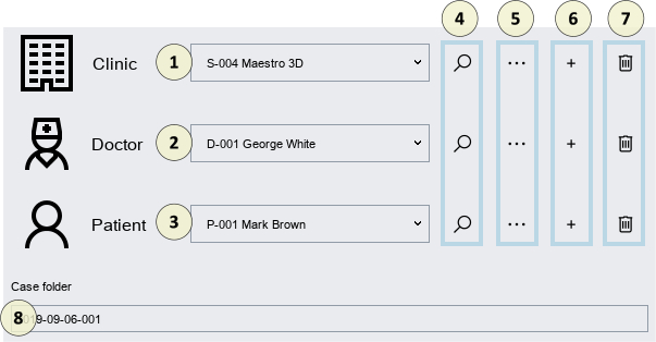
Clinic, doctor and patient management
- 1 List of clinics;
- 2 List of doctors;
- 3 List of patients;
- 4 Search. By entering a textual value (for example part of the name or surname), the relative drop-down menu will be populated only by the elements that respect the search criteria;
- 5 Edit. A tab will appear through which it will be possible to change the data of the selected item;
- 6 Add. A tab will appear through which it will be possible to enter the values of the registry;
- 7 Delete. Delete the currently selected item in the list;
- 8 Work case save folder. It is advisable not to change this value, all work cases, as a default choice, are saved in the C:\MaestroData folder.
|
ADVICE make periodic backups of the C:\MaestroData folder. |
In the phase of creating a new case, one must then select the clinical triad, doctor, patient who will identify the work case.
With this selection the selected doctor will be associated to the selected clinic and the selected patient to the selected doctor.
|
ADVICE: do not associate the same doctor with several clinics; do not associate the same patient with more doctors. |
Input file for an orthodontic case
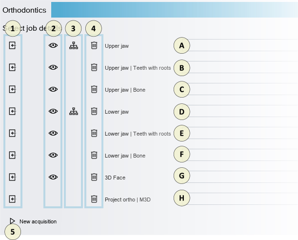
- 1 Upload input file from disk;
- 2 Displays a preview of the uploaded file;
- 3 Select the file from the list of scans (only if you have a 3D Maestro scanner);
- 4 Delete the input file loaded;
- 5 Start a new scan (only if you have a 3D Maestro scanner).
- A Upper model;
- B Upper model of crowns and roots obtained from the segmentation process of a file from CBCT. This will be used to combine the scanned crowns with the real roots;
- C Upper model of the bony part (maxilla);
- D Lower model;
- E Lower model of crowns and roots obtained from the segmentation process of a file from CBCT. This will be used to combine the scanned crowns with the real roots;
- F Lower model of the bony part (mandible);
- G 3D model of the face scan;
- H Project files * .ortho (v4) or * .m3d (v5);
To achieve an orthodontic work case, at least one arch (upper or lower) must be loaded.
To start the new case press the 'Next' 'button.
Open an existing work case
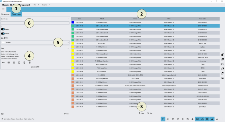
- 1 Open case of work tab;
- 2 List of work cases;
- 3 Buttons to change page, move to the beginning, to the end of the list of work cases;
- 4 Information and tools related to the selected work case;
- 5 Drop-down menu to display the list of cases according to a time span, (cases of today, yesterday, one month old, ...);
- 6 Search. By entering a search string, only the work cases that meet those criteria will be displayed. The patient, doctor or clinic item can be ticked if we want the research to have an effect on these 3 elements. For example, if we enter the name or part of a patient in the search string, all cases related to that patient will be displayed. To cancel the search, simply delete the search string and press the enter key on the keyboard.
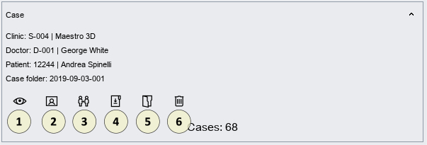
- 1 Preview of the currently selected work case;
- 2 Associate the currently selected work case with a different patient;
- 3 Clone the case case of currently selected work;
- 4 Change the name of the folder related to the currently selected work case;
- 5 Open the folder for the currently selected work case with the Windows file manager;
- 6 Delete the currently selected work case.
All these tools mentioned above are also accessible via the context menu of the work case.
To open a case, you can double-click on the work case or press Preview and then press Next.
Dental Studio User Interface
The image below shows how the software user interface appears.
- 1 Main Toolbar;
- 2 Display and work area;
- 3 Sidebar;
- 4 Display Toolbar;
- 5 Information area.
1 - Main Toolbar
- 1 File menu;
- check the updates;
- exit from the software;
- 2 Help menu;
- guide;
- displays information about the software version and the license;
- 3 Settings menu | change language, colors, display settings and autosave;
- 4 Capture screen menu;
- 5 Record a video menu;
- 6 Home tab;
- 7 Analysis and Measurements tab;
- 8 Virtual Setup tab;
- 9 Save project;
- 10 Close and return to Order Management;
- 11 Export;
- export study models;
- export M3D project for the viewer;
- 12 Reference system;
- 13 Change Articulation;
- 14 Study models | virtual bases;
- 15 3D labels on the study models;
- 16 Removal of brackets from the input arches;
- 17 Modeling tool | add, remove material | smooth the surface;
- 18 Note;
- 19 Multiple canonical views;
- 20 2D image collection.
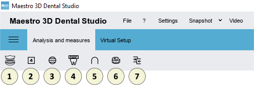
- 1 Occlusal inspection;
- 2 4D Motion;
- 3 3D sections;
- 4 Mesio-distal measurements | Bolton analysis;
- 5 Measurement of the length of the arch;
- 6 Free measures | point-to-point | angles;
- 7 3D comparison.
- 1 Teeth segmentation;
- single cutting line for each tooth;
- global cutting line;
- set tooth axes | center of rotation | FA point | initial Tip and Torque;
- 2 Virtual Setup;
- virtual setup;
- Import new attachments;
- 3 Brackets positioning;
- brackets positioning;
- brackets library;
- 4 Construction of transition models;
- 5 Clear aligners;
- clear aligners;
- clear aligners for attachments positioning;
- clear aligners for brackets positioning;
- clear aligners (with window) for brackets positioning;
- clear aligners for brackets with jigs positioning;
- 6 Cut and close;
- cut and close with line;
- cut and close with plan;
- 7 3D labels on transition models;
- 8 Drop-down menu of transition models for the upper and lower arch;
- 9 Treatment animation and speed control;
- 10 PDF report;
- 11 Video report;
- 12 Export;
- export clear aligners;
- export guide templates for attachments;
- export clear aligners for brackets positioning;
- export clear aligners (with window) for brackets positioning;
- export clear aligners for brackets with jigs positioning;
- export scanned model with the transfer keys for brackets;
- export transition models.
2 -Display and work area
The display and work area is the area of the window where the 3D models are displayed and where editing operations are allowed. In the display area it is possible to view / create the virtual bases, view the occlusion between the maxilla and the mandible, view the measurements of the teeth, the length of the arch and realize and show the virtual setup and all the other phases of the work.
To examine the displayed models, the chamber parameters (position, scaling, rotation) can be set using an instrument called trackball. The trackball is a simple tool to use to move and interact with the 3D scene.
- Press and drag the left mouse button to rotate around the model;
- Rotate the middle mouse wheel to zoom;
- Press the middle mouse button or the wheel to change the center of rotation of the 3D scene;
- Press and drag the right button to move the camera.
3 - Sidebar
|
4 - Display toolbar
- 1 Show / hide and change the transparency of the 3D scene components;
- 2 Enable the wheel or drag mode for the touchscreen;
- 3 Enlarge [PGDown key] / make the 3D scene smaller [PGUp key];
- 4 Reset the view;
- 5 Change the projection of the camera that frames the 3D scene: parallel projection [key O], perspective projection [key P];
- 6 Change the lighting properties of 3D models: smooth shading [S key], flat shading [F key];
- 7 Enable photorealism;
- 8 Enable shadows (only if photorealism is active);
- 9 Show / hide the real color of the 3D models, if the actual color was acquired during the scan;
- 10 Show / hide the triangles;
- 11 Show / hide the triangle borders [E key];
- 12 Show / hide points [V key].
5 - Information area
The information area located in the lower left corner of the main screen, contains all the main information of the work case. For example, the name of the clinic, the doctor, the patient data, the identification of the work case and the currently displayed models are shown.
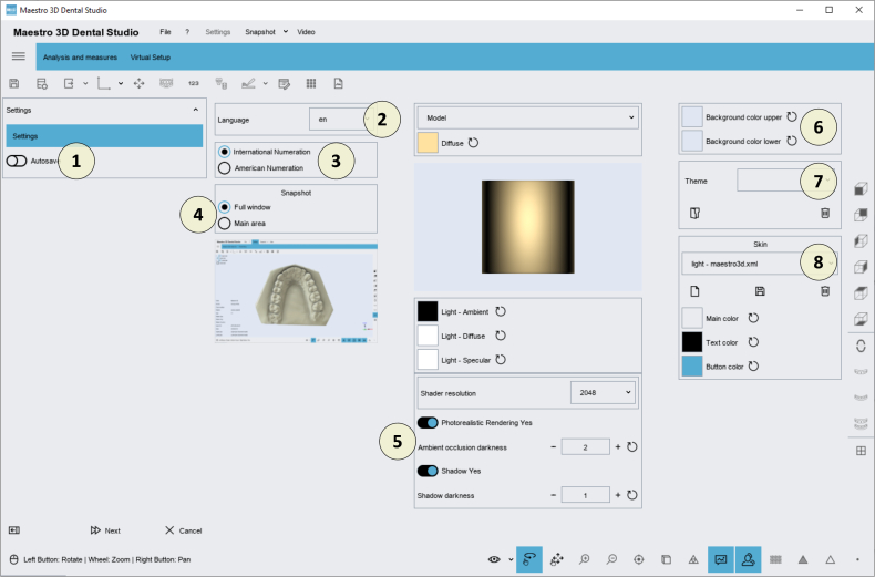
Settings
As shown in the figure, press on the menu 1 item:
The software will show a screen like the one shown in the figure below::
- 1 AutoSave;
- 2 Change interface language;
- 3 Numbering (International, American);
- 4 Screen capture mode;
- 5 Render Settings;
- 6 Background color;
- 7 Background image;
- 8 User interface color scheme.
FAQ
How can I see the software version? Active modules? The license serial number?
As shown in the figure, activate the menu 1 e and press 2.
The software will show a screen like the one shown in the figure below:
- 1 License serial number;
- 2 Copy the license serial to the clipboard;
- 3 Software version number;
- 4 Maximum version available to which the license can be updated;
- 5 Shows if new updates are available;
- 6 For all the modules in the software version, it shows the active and the inactive ones;
- 7 Close the screen.
How can I find out if my software version is updated to the latest one available?
As shown in the figure, activate the menu 1 e and press 2.
A message will show if there are any updates or not.
What features must the input models have?
Input models must be STL\PLY\OBJ files recorded in the correct occlusion;
- They must not contain tunnels;
- They must not contain handles;
- They must be manifolds;
- They must not have holes;
- They must not have degenerate triangles (eg triangles with zero area);
- They must not have duplicate triangles;
- They must not have unreported vertices;
- The triangles must all have the same orientation;
|
ADVICE: By using the Maestro 3D scanner you have the guarantee that the input models fully comply with the software requirements without having to use third-party programs to repair the models. |
