Maestro 3D Easy Dental Scan - Руководство пользователя
Описание и назначение Maestro 3D
Цель этого документа - познакомить пользователя с использованием сканера Maestro 3D простым и быстрым способом.
Пожалуйста, внимательно прочитайте это руководство.
Maestro 3D – Это программно-аппаратный комплекс состоящий из сканера Maestro 3D Scanner и программного обеспечения Maestro Easy Dental Scan управляющего работой сканера.
Maestro 3D – предназначен для получения 3D-образа матовых (не блестящих) моделей с габаритами не более 90х90х60мм (X/Y/Z), лицами обладающими навыками работы с САПР.
Maestro 3D Scanner - это стационарное периферийное устройство, анализирующий форму предмета, помещенного в сканер, посредством анализа отраженного света проецируемого на исследуемый объект, и на основе полученных данных создающее его 3D-модель.
Полученные методом сканирования 3D-модели в дальнейшем могут быть сохранены и обработаны средствами САПР.
Maestro Easy Dental Scan - это программное обеспечение, которое управляем работой 3D-сканеров Maestro. Программное обеспечение позволяет автоматически получать 3D объекты одним щелчком мыши и создавать трехмерные поверхности полученных данных полностью автоматически, без какого-либо вмешательства пользователя.
Сборка компонентов
Сборка калибровочного комплекта
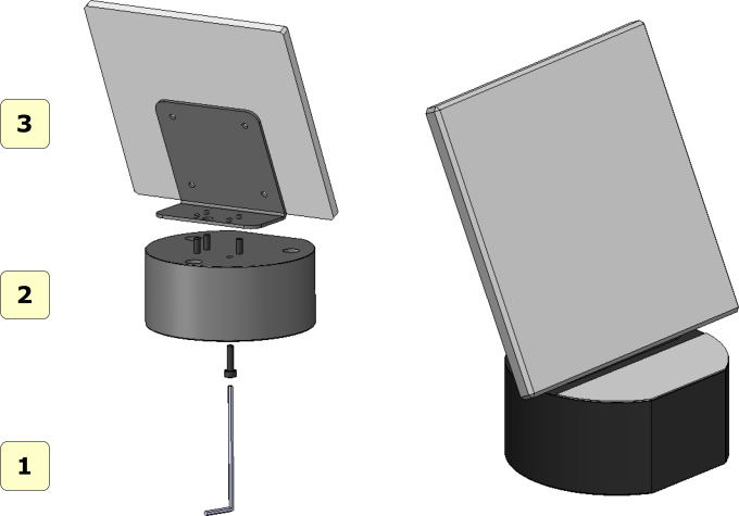
См. Рисунок ниже, показывающий, как следует собирать калибровочный комплект после извлечения его из упаковки.
- 1 шестигранный ключ;
- 2 тарелка;;
- 3 калибровочная пластина;
Просто прикрутите 4 прилагаемых винта, чтобы соединить пластину с калибровочной пластиной. Будьте осторожны, чтобы не поцарапать и не испачкать калибровочную пластину. Рекомендуется обращаться с пластиной в перчатках, чтобы не испачкать ее и не оставить на ней отпечатки пальцев.
|
ПРЕДУПРЕЖДЕНИЕ
|
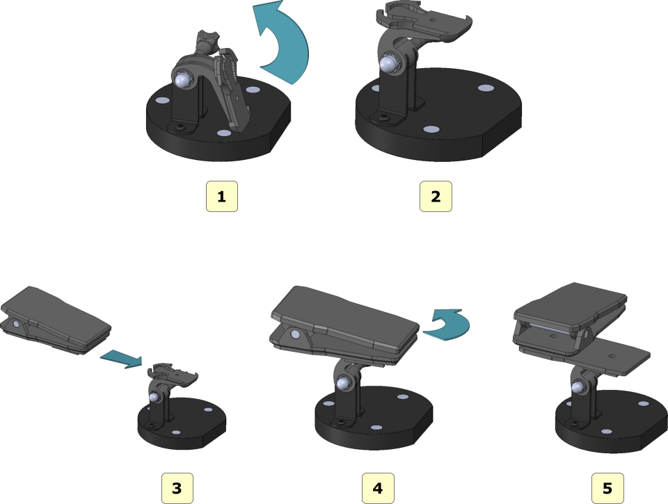
Сборка держателя для оттисков
Выполните шаги, как показано на рисунке, чтобы правильно собрать оттискную пластину после извлечения ее из упаковки.
Планшеты для сканирования
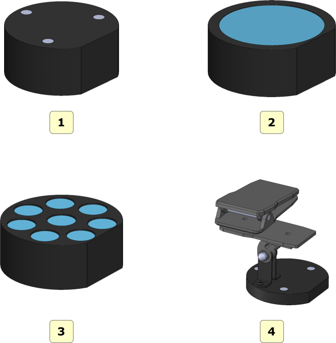
На рисунке ниже показаны все сканирующие пластины, поставляемые со сканером MDS500::
- 1 интерфейсная пластина;
- 2 пластина для модели дуги;
- 3 пластина для штампиков;
- 4 пластина для оттиска;
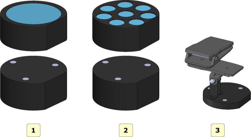
Варианты использования планшетов при сканировании
- 1 используйте эту конфигурацию для сканирования одной зубной дуги или верхних и нижних дуг при окклюзии;
- 2 использовать эту конфигурацию для сканирования съемных штампов;
- 3 используйте эту конфигурацию для сканирования оттисков;
UAC - Контроль учетных записей пользователей
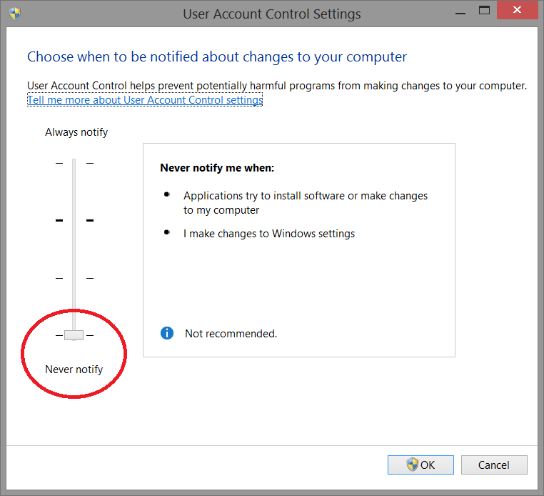
Чтобы избежать трудностей и ограничений в использовании Программного обеспечения, необходимо установить для ползунка UAC - Контроль учетных записей пользователей минимальное значение, как показано на рисунке ниже.
Чтобы войти в окно настроек: Панель управления-> Учетная запись пользователя-> Изменить настройки учетных записей пользователей. (Control panel-> User Account-> Change Settings User Account Control)
Права Администратора
Для запуска Программного обеспечения необходимо правильно установить права администратора.
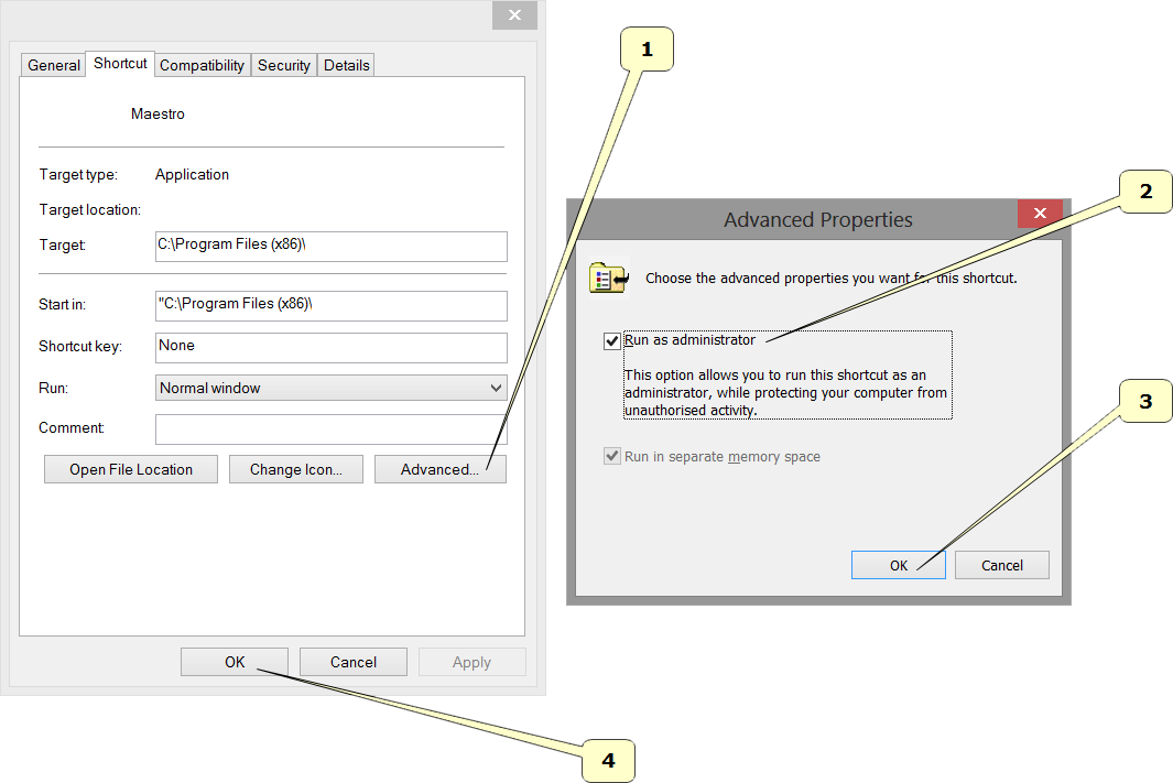
Следуйте инструкциям, как показано на картинках ниже.
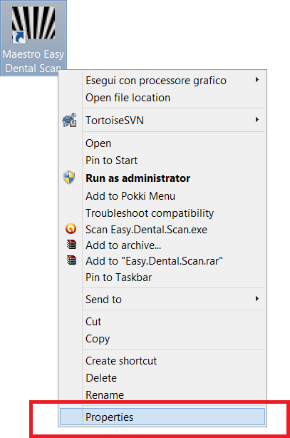
Правая кнопка мыши на значке программного обеспечения, чтобы запустить контекстное меню и выбрать свойства записи.
Выполните шаги, как показано в последовательности от 1 до 4.
- Нажмите кнопку Дополнительно.
- Выберите пункт Запуск от имени администратора.
- Нажмите кнопку Ok.
- Нажмите кнопку Ok.
Пользовательский интерфейс
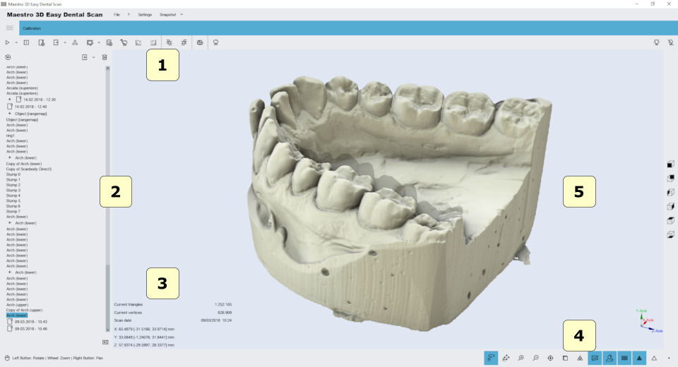
На рисунке ниже показана структура пользовательского интерфейса.
- 1) Основная панель инструментов.
- 2) Область деревьев.
- 3) Информационная зона.
- 4) Нижняя зона.
- 5) Визуализация \ Область редактирования.
Главная панель инструментов
Основная панель инструментов обеспечивает доступ ко всем функциям программного обеспечения Easy Dental Scan.
- 1) Новое сканрование - начать новое сканирование или определить новую стратегию сканирования.
- 2) Scanner Status - активирует окно, которое отслеживает состояние аппаратного сканера.
- 3) New Group - добавляет новую группу в дерево. Можно перемещать элементы дерева внутри / снаружи группы перетаскиванием мышью.
- 4) Export - Экспорт выбранного элемента по оси Z или Y. Вы можете экспортировать в открытый файл STL или PLY.
- 5) Postprocess (преобразование отсканированных данных в 3D-модель) - функция активируется, если элемент выбран, а не подвергнут последующей обработке. Эта операция может занять несколько минут для преобразования отсканированных данных со сканера в треугольную геометрию.
- 6) Editing filter - Редактировать выбранные элементы. Это полезно для удаления артефактов из-за сканирования, для удаления отсканированной замазки, для выполнения заполнения отверстий, прореживания, редактирования 2D \ 3D выбора и т. д.
- 7) Import a scanbody from library.
- 8) автоматическая процедура выравнивания штампов.
- 9) установить выбранный элемент как фиксированный или плавающий в процедуре ручного выравнивания.
- 10) Сравнение.
- 11) Измерения:
- точечные измерения.
- угловые измерения.
- 12) CAD - отправить выбранные элементы в программное обеспечение для проектирования.
- 13) Статус проектора.
- Включить.
- Выключить.
Калибровка описана здесь: Калибровка.
Нижняя панель инструментов
Нижняя панель инструментов - это область экрана, содержащая индикатор выполнения, который отображается и обновляется при каждом вычислении программы, а также элементы управления для изменения визуальных настроек области визуализации / редактирования.
- 1) режим сенсорного экрана (поворот / панорамирование).
- 2) увеличить в [клавиша PGDown] / увеличить в [клавиша PGUp].
- 3) сброс трекбола [клавиша R].
- 4) параллельная проекция [клавиша O], перспективная проекция [клавиша P].
- 5) плавное затенение [клавиша S], плоское затенение [клавиша F].
- 6) фотореалистичная визуализация.
- 7) тень, (доступно, если фотореалистичный рендеринг включен).
- 8) цвет текстуры, (цвет реального объекта).
- 9) sпоказать / скрыть треугольники, ребра [клавиша E], вершины [клавиша V].
Область визуализации / редактирования и область информации
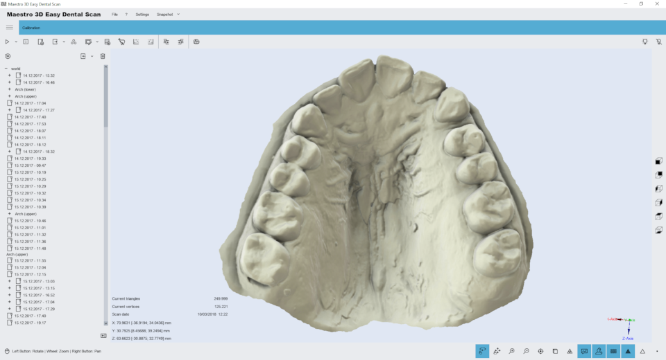
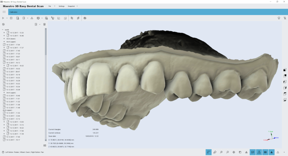
Область визуализации / редактирования - это область окна, в которой модели визуализируются и выполняются все операции редактирования.
В области визуализации можно видеть модели, редактировать и измерять расстояние между различными точками.
Для просмотра моделей, отображаемых в области визуализации / редактирования, параметры камеры (положение, масштаб и поворот) можно настроить с помощью инструмента, называемого трекбол.
Трекбол очень прост в использовании. Просто используйте левую кнопку мыши для поворота вокруг модели, колесико мыши для увеличения / уменьшения масштаба и правую кнопку мыши для перемещения (панорамирования) камеры.
В информационной области экрана отображается информация, относящаяся к текущему элементу.
Область дерева
Область дерева содержит все отсканированные модели. Использование групп позволяет сохранять порядок отсканированных моделей. Чтобы выбрать модель из области дерева, просто нажмите на нее левой кнопкой мыши. Выбранные модели будут отображены в области визуализации. Чтобы выбрать больше моделей, нажмите и удерживайте клавишу CTRL \ SHIFT.
Область дерева может содержать следующие элементы:
| |
Штамп |
| |
Верхняя челюсть |
| |
Нижняя челюсть |
| |
Верхняя \ Нижняя десна |
| |
Верхний \ Нижний Waxup |
| |
Соотношения челюстей |
| |
Rangemap |
| |
Группировка |
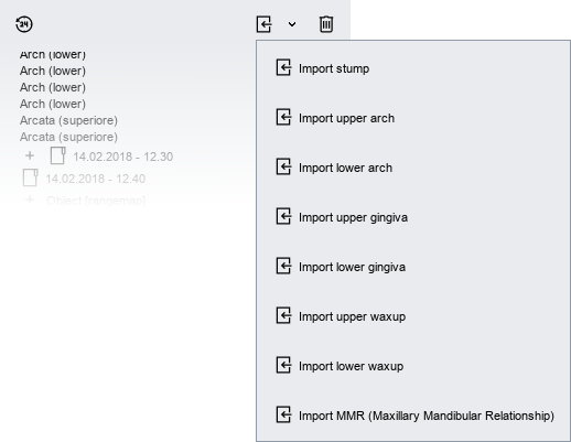
Каждому из этих элементов соответствует набор операций, доступных через включенные значки на главной панели инструментов. Это позволяет пользователю получить доступ к основным функциям программного обеспечения.
Получив доступ к раскрывающемуся меню, как показано на следующем рисунке, вы можете импортировать в дерево файл STL.
Целевые объекты
Некоторые примеры целевых объектов:
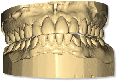
- Отношения верхней и нижней челюсти
- Верхняя - Нижняя Челюсть
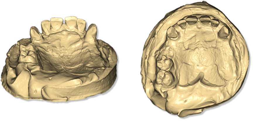
- Другие примеры зубной дуги
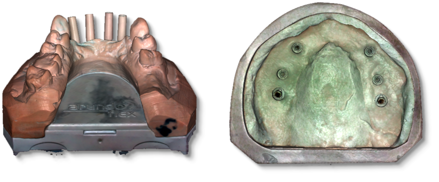
- Оттиски
- Штампы
Правильное расположение объектов
Дуга или MMR
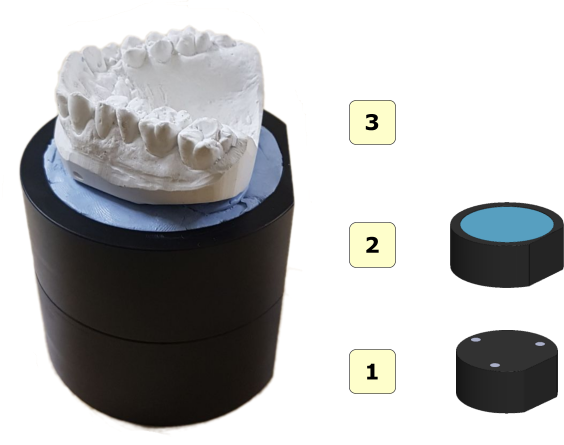
На следующих изображениях показано правильное расположение моделей на поворотном столе. На рисунке ниже показана арка, правильно расположенная на поворотном столе. Арка должна быть размещена в центре поворотного стола, поддерживаемого замазкой или любым другим клеем, который удерживает ее хорошо прикрепленной к столу.
Арка должна быть параллельна поверхности и не должна быть наклонена.
- 1 интерфейсная пластина;
- 2 пластина для модели;
- 3 объекта для сканирования, дуги или нижнечелюстные отношения нижней челюсти (MMR);
Штампы
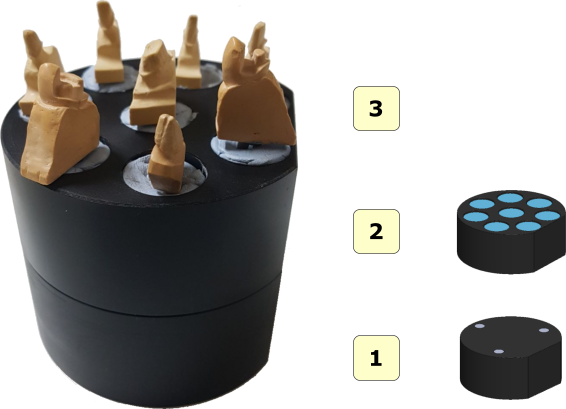
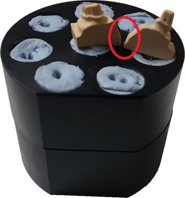
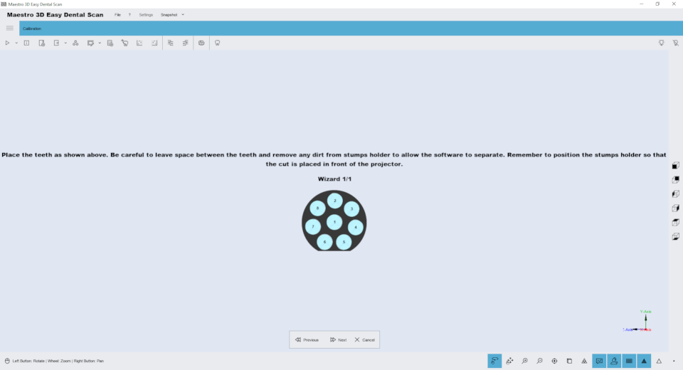
На поворотный стол сканера можно расположить до 8 штампов одновременно.
- 1 интерфейсная пластина;;
- 2 пластина для штампов;
- 3 штампы;
После процесса сканирования программное обеспечение автоматически распознает и разделяет отдельные штампы, добавляя элемент в области дерева для каждого полученного штампа. Нумерация (1..8) на табличке соответствует нумерации элементов, добавляемых в область дерева, только если табличка размещена перед сканером.
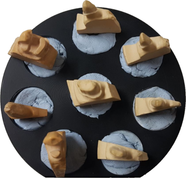
Пример правильного позиционирования:
При работе с более чем с 1 штампом абсолютно необходимо, чтобы клейкие замазки, поддерживающие штампы, и тело каждого штампа были отделены, по крайней мере, на несколько миллиметров друг от друга. Таким образом, программа сканирования может распознавать каждый штамп,
Пример неправильного позиционирования:
|
ПРЕДУПРЕЖДЕНИЕ. На рисунке выше показано неправильное расположение штампов. Опора замазки каждого штампа не должна соединяться, а тела штампов не должны касаться или не должны быть слишком близко, потому что это неправильное расположение не позволяет сканирующему программному обеспечению идентифицировать и отделять отдельные элементы. |
|
СОВЕТ Штампы не следует размещать с чрезмерным наклоном, так как сканер не может в этих условиях получить всю граничную линию. Поэтому всегда следует размещать штампы перпендикулярно поверхности поворотного стола. |
Оттиски
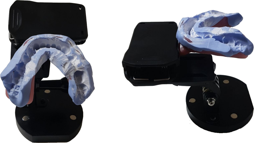
На следующих изображениях показано правильное расположение оттисков на вращающемся столе. Эта система фиксации, используемая вместе с функцией сканирования Smart Impression, доступна только для моделей MDS 500. На изображении ниже показан оттиск, правильно расположенный на вращающемся столе. Оттиск должен быть прикреплен к специальному зажиму так, чтобы он находился в центре вращающегося стола. Вы также можете использовать колесо для регулировки угла.
Нет необходимости использовать другие пластины, система фиксации оттиска должна быть расположена непосредственно внутри сканера.
|
СОВЕТ
|
3D сканирование
Параметры сканирования
Чтобы начать новое приобретение, просто нажмите Новое приобретение на главной панели инструментов.
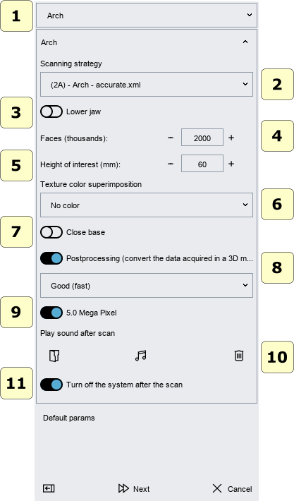
В этом окне вы можете выбрать тип проверяемого объекта и параметры сканирования.
- 1 object type (арка, десна, восковая спинка, штампы, слепок, челюстно-нижнечелюстная связь, ...).
- 2 scanning Strategy: можно выбрать стратегию сканирования.
|
ПРЕДУПРЕЖДЕНИЕ Может случиться, что при небольшом количестве поступлений (например, 4-5) для некоторых моделей может не получиться выполнить сканирование, поскольку геометрия перекрытия между различными снимками недостаточна. В этом случае достаточно увеличить количество приобретений в стратегии. |
- 3 верхняя или нижняя модель..
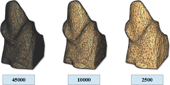
- 4 грани (треугольники):
Это число определяет количество треугольников, которые вы хотите в вашей окончательной модели. На рисунке ниже показана та же модель с 45000, 10000 и 2500 треугольниками. Точность и точность в 3 моделях эквивалентны. Среди 3 моделей изменяется количество треугольников, которые приближают геометрию поверхности. Система всегда получает максимальную точность и максимальную точность. Только после получения окончательной трехмерной модели с максимальным количеством треугольников, она уничтожается для получения желаемого количества треугольников. Также возможно уничтожить модель позже.
|
ВНИМАНИЕ! Чем больше количество треугольников, тем больше размер файла STL.
|
|
СОВЕТ Рекомендуемые значения :
|
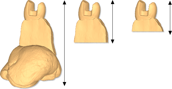
- 5 высота интереса::
Этот параметр позволяет вам выбрать интересующую вас высоту модели (это значение высоты измеряется сверху вниз).
На первом рисунке (слева направо) показана модель штампа, в котором параметр высоты интереса отключен, а затем Штамп приобретается полностью, включая поддерживающую его клеевую подложку. Последующие изображения показывают ту же самую культю с параметром высоты интереса, установленным на 20 мм и 15 мм соответственно (как можно видеть, клеевая опора шпатлевки автоматически удаляется).
Важно помнить, что для наилучшего использования этого параметра модель (дуга, один или несколько штампов и т. Д.) Должна располагаться перпендикулярно поверхности поворотного стола.
|
ВАЖНО Вырежьте модель, выбирая интересующую высоту, сокращает время вычислений постобработки и может улучшить качество результатов. (Особенно маленький объем облака точек штампов может привести к лучшей урожайности конечной модели). |
В любом случае вы всегда можете удалить неинтересную геометрию в любое время, отредактировав модель.
- 6 цвет наложения текстуры:
Для этого требуется активный модуль наложения текстур. Активация осуществляется через лицензию на программное обеспечение. Это полезно для получения моделей с цветовой текстурой RGB или серой текстурой. Например, это помогает создать очень точные линии полей, как отмечено на модели.
- 7 закрыть базу:
Если этот параметр установлен, программное обеспечение автоматически закроет нижнюю базу модели.
- 8 постобработка (преобразование данных, полученных в 3D-модель):
Если эта опция включена, система автоматически постобрабатывает полученные данные и строит поверхность треугольной геометрии. Если этот флажок не установлен, данные не будут подвергаться последующей обработке. Возможна постобработка данных, полученных позже.
- Хорошая (быстро): этот вариант рекомендуется..
- Лучшая (медленно): эта опция требует больше времени для вычислений и создает 3D-модели с большим количеством деталей..
|
СОВЕТЫ Чтобы сократить время взаимодействия со сканером, когда у вас есть много моделей для сканирования, желательно не выполнять постобработку после каждого сканирования. В этом случае рекомендуется сканировать все модели (не проверять опцию «Постобработка», не проверять опцию «Выключить») и по окончании работы выключать систему и выбирать из области дерева все элементы (карты диапазонов) и нажмите кнопку для последующей обработки всех моделей. |
- 9 Разрешение камеры, (доступно только со сканером модели MDS 500).).
- 10 воспроизведения звука после сканирования:
Можно выбрать файл * .wav для воспроизведения после сканирования и после постобработки.
- 11 выключите систему после сканирования:
Выключение системы после окончания сканирования.
|
СОВЕТЫ Не забывайте выключать систему, когда она не используется, чтобы избежать выгорание лампы. |
Процесс сканирования
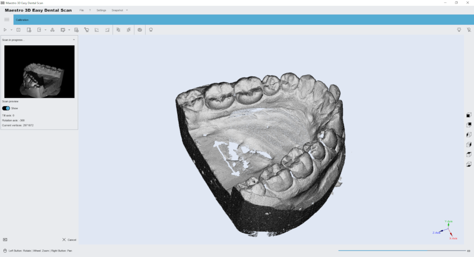
Это окно показывает прогресс фазы сканирования. Это может занять несколько секунд или несколько минут в зависимости от выбранной стратегии. В окне слева показано получение 2D изображения и 3D изображения справа.
После этой операции, если была отмечена опция «Постобработка», программа автоматически генерирует поверхность модели из полученных точек и добавляет в область дерева новый элемент. Затем, выбрав его в области дерева, модель отобразится в области визуализации.
Если опция «Постобработка» не была отмечена, программа добавляет в область дерева новый элемент со значком серого. Прежде чем вы сможете выполнить какую-либо операцию этой модели, необходимо выполнить постобработку полученных данных.
|
ПРЕДУПРЕЖДЕНИЕ Перед сканированием убедитесь, что модель правильно расположена на поворотном столе и передняя дверца сканера закрыта. Во время сканирования не перемещайте ни сканер, ни его опорную плоскость. |
Стратегия сканирования
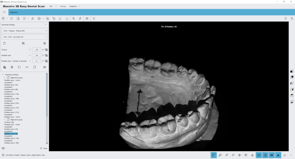
На следующем рисунке показано окно для управления стратегиями сканирования.
Подробности смотрите ниже:
- 1) Группа сканирования: MMR, Арка, Штампы, Оттиск.
- 2) Название стратегии.
- 3)
- Новая стратегия.
- Сохранить текущую стратегию.
- Удалить текущую стратегию.
- 4) Добавить команду наклона (перед добавлением команда выбирает градусы поворота).
- 5) Добавить команду вращения (перед добавлением команда выбирает градусы вращения).
- 6) Добавить пакетное приобретение. (перед добавлением команды выберите количество шагов поворотного стола оси вращения).
- 7) Команды:
- Очистить все команды.
- Удалить выбранную команду.
- Добавьте команду наклона исходного положения.
- Добавьте команду поворота в исходное положение.
- Добавьте группу выравнивания.
- Добавьте одно приобретение.
- Запустите симуляцию стратегии.
|
СОВЕТЫ:
|
Сканирование оттисков
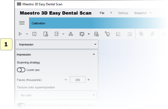
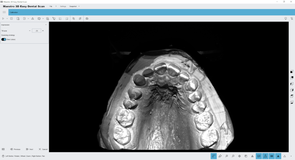
На следующем изображении подробно показаны параметры, которые будут выбраны для сканирования оттиска:
- 1 выберите Оттиск из раскрывающегося меню и выберите остальные параметры по своему усмотрению.
Предварительно просмотрите правильное расположение слепка на соответствующей пластине слепка : #Impression
На изображении ниже показан следующий шаг.
На этом этапе двигатель наклона должен быть отрегулирован так, чтобы иметь возможность визуализировать Оттиск, как показано на рисунке выше. Цель состоит в том, чтобы дать программному обеспечению превосходную точку зрения, например, на то, что резцы отчетливо видны как вестибулярно, так и язычно. Начиная с этой точки, программное обеспечение будет строить стратегию динамического сканирования, которая позволит получить максимально возможное Оттиск. Попробуйте отрегулировать значение наклона так, чтобы резцы были видны как можно больше. Давайте подробно рассмотрим интерфейс инструментов:
- 1 нажмите кнопку + или -, чтобы переместить ось наклона;
- 2 выберите это, если вы хотите использовать лучшую стратегию. Это занимает больше времени, но гарантирует больший охват;
|
СОВЕТЫ:
|
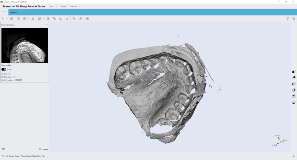
Следующим шагом, как показано на рисунке ниже, является фаза сканирования. На этом этапе важно, чтобы дверца сканера была закрыта, чтобы окружающий свет не мешал, уменьшая контраст структурированного света. Не менее важно, чтобы сканер был установлен на устойчивом столе, и чтобы он не подвергался ударам или вибрации на этом этапе.
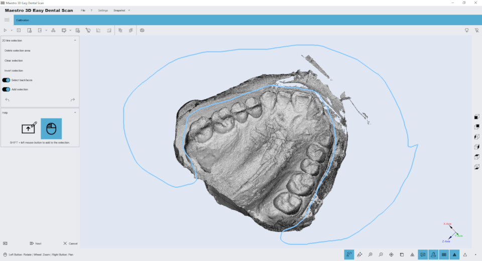
После завершения сканирования оттисков программное обеспечение позволяет «очистить» отсканированное изображение перед его обработкой. Смотрите также функцию #Editing_with_2D_selection. На этом этапе, как показано на рисунке ниже, можно удалить все лишние части сканирования.
Таким образом, этап постобработки, который преобразует облако точек в трехмерную модель, будет быстрее и эффективнее.
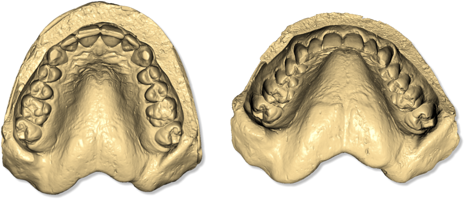
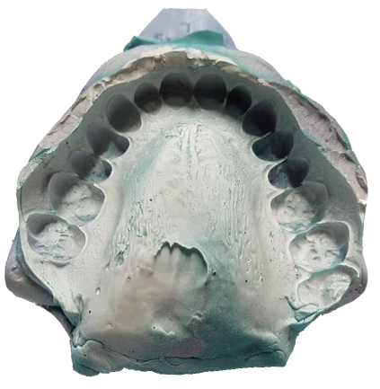
Ниже вы можете увидеть готовый результат сканирования оттисков: фото реального оттиски Регистрация штампов
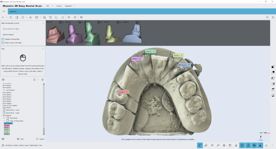
Stumps registration
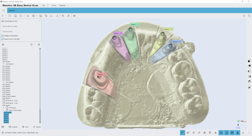
The registration of stumps is totally automatic and it allows to replace the low resolution stumps, acquired with the arch, by the high resolution stumps acquired without the arch.
Select into the Tree Area the arch with the stumps (which are to be replaced).
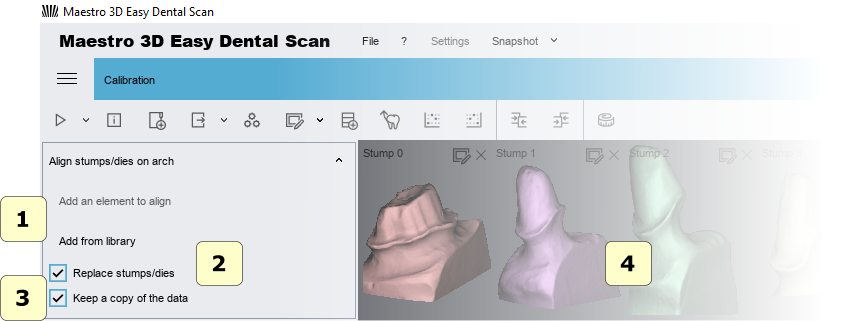
After the arch is displayed in the Visualization Area with a constrained view so that it can be inspected only from above. In details:
- 1) to add the stumps\scan body to substitute, select these from tree area and press the buttons.
- 2) if replace stumps is checked, the high resolutions of the single stump will be replaced with the lower resolutions stump scanned with the arch. This is recommended if you need to work with a dental cad software. If not select this option the stump will be only aligned.
- 3 if this option is checked the software make a backup copy of the data.
- 4) preview area of the stumps.
|
TIP: If the selected stump is not the correct stump, just close the preview window to remove it from the registration process. You can register up to 16 stumps simultaneously. |
After having selected and added the stumps, press double click with the left mouse button over the center of the head of the low resolution stumps to indicate the position where every stump must be registered.
By double clicking over the head of the stumps, it is added to the Visualization Area a sphere (called marker) associated with a number. Color and number, as shown in the picture, these are associated with the right stump.
|
TIP: To remove a marker double-click on it. |
Before to proceed with the registration, please make sure that each marker is associated with the right stump. To proceed with the registration press the Next button.
A progress bar placed in the Bottom Toolbar will indicate the progress of the registration process.
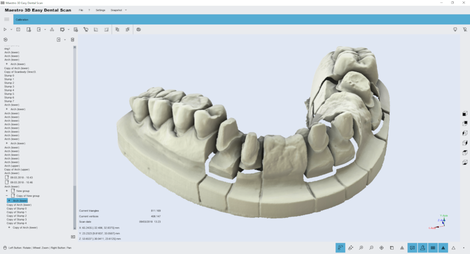
At the end of the registration process the result of the registration is displayed in the Visualization Area, where low resolution stumps have been replaced with high resolution stumps.
If you are satisfied with the result press the button Next to finish and save the registration obtained or press the previous button to return to previous step.
If one or more stumps are not correct aligned, press the close button near the marker and then after having completed this task you can re-register only those stumps.
If the registration is not satisfactory, please verify that markers have been placed in the correct position as explained previously (in the center of the head of each stump and in the correct order).
|
TIP: It is also possible substitute the stumps on the arch with a manual alignment. |
Manual 3-2-1 alignment
With the manual registration process, is possible to align any pair of models. For example useful to align a stump on an arch or an arch or bite with a antagonists reference model.
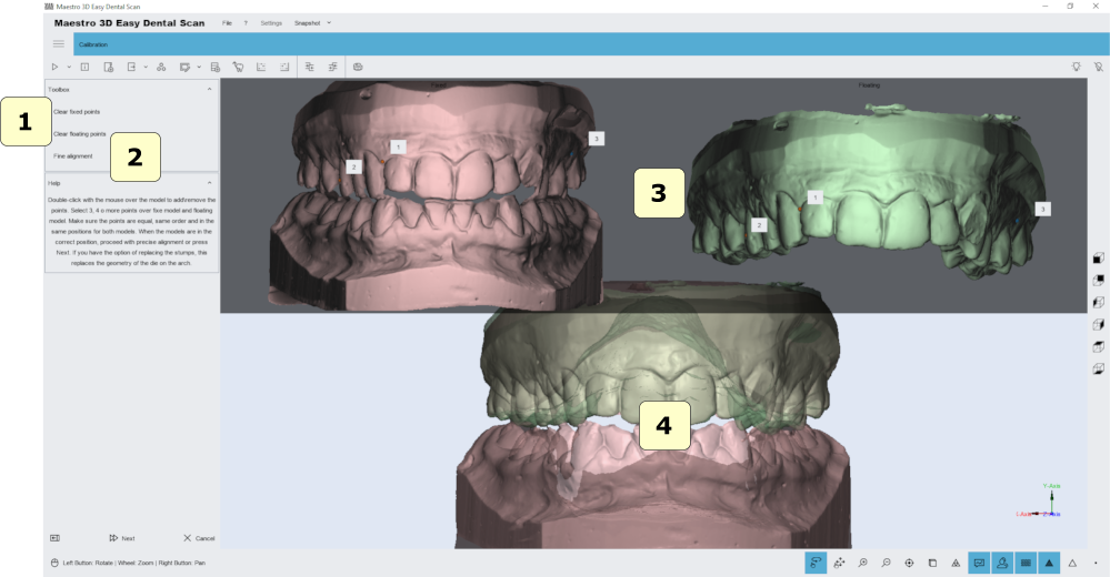
To align two models, need to select the fixed model (example maxillary mandibular relationship) and the floating model (example arch). The next image shows the manual alignment window.
To align the floating object over the fixed object, you have to add some points in the fixed model (that appears to the left of the screen) and the same points should be added to the floating object (that appears to the right of the window). You must add at least 3 points on each model.
- 1) clear fixed or floating point.
- 2) fine alignment. Improves the initial alignment given by the points entered by the user.
- 4) preview area where are showed the fixed and floating model.
- 5) alignment result.
|
TIP: Press double click with left mouse button to add a point over the model. |
Editing Filters
Editing with 2D rectangle
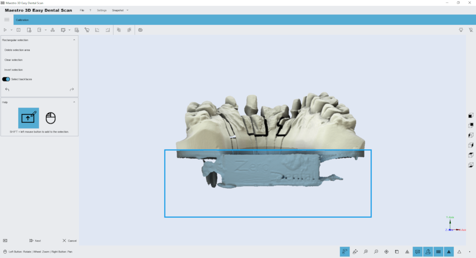
Editing features of the rectangular selection. The image below shows the filter window.
Holding down the SHIFT key and the left mouse button you can draw a rectangular selection area. The area of the selected geometry will appear colored red. In the toolbox on the left side of the screen there are buttons to delete the selected area, invert the selection, clear the selection. To save the changes and return to the previous screen, press the button Next.
Editing with 3D polyline
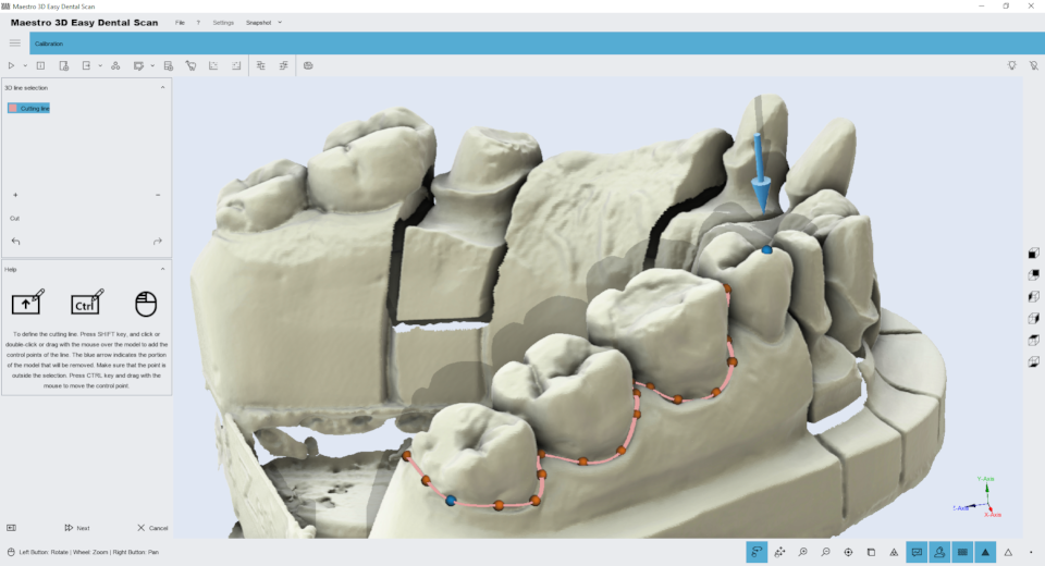
Editing features of the 3D polyline selection. The image below shows the filter window.
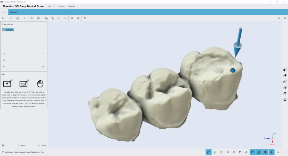
Holding down the SHIFT key and the left mouse button you can draw a 3D polyline over the model. This function is useful to remove the gum or the waxup from a model. After you have drawn the polyline just double click into the area that you want to delete. The image below shows the result of the filter.
To save the changes and return to the previous screen, press the button Next.
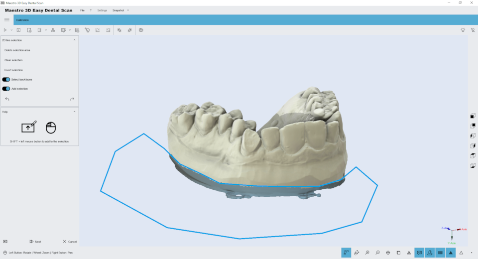
Editing with 2D selection
Editing features of the 2D selection. The image below shows the filter window.
Holding down the SHIFT key and the left mouse button you can draw a 2D selection area. The area of the selected geometry will appear colored blu. In the top of the screen there are buttons to delete the selected area, invert the selection, clear the selection. To save the changes and return to the previous screen, press the button Next.
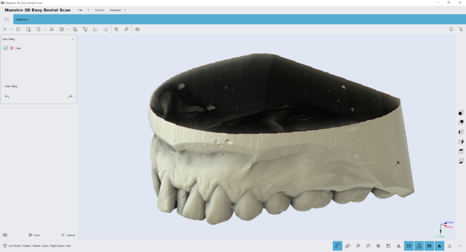
Holefilling
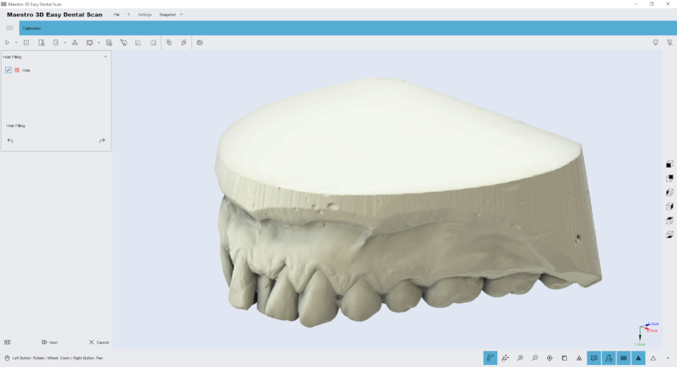
Editing feature of holefilling. The image below shows the filter window.
Just press the button Hole filling in the toolbox on the left side of the screen to filling all holes in the model. This is useful to fill the bottom of the base of a model. The image below shows the result of the filter.
To save the changes and return to the previous screen, press the button Next.
Decimation
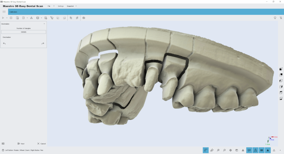
Editing feature of decimation. With this feature it is possible to reduce the number of triangles of the model. The filter removes more triangles in the model areas with less features, keeping better details in the most important areas of the model as the margin line or the teeth geometry. The image below shows the initial model at 700,000 triangles:
Just choose the triangles number and press the button Decimation in the toolbox on the left side of the screen to reduce the number of triangle of the model. To save the changes and return to the previous screen, press the button Next.
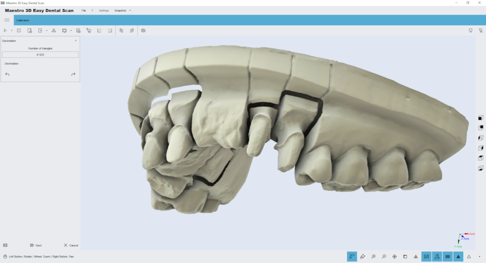
The image below shows the same model with a quarter of resolution, 160,000 triangles. As you can see, there is no loss of detail and the margin lines are still very visible and detailed.
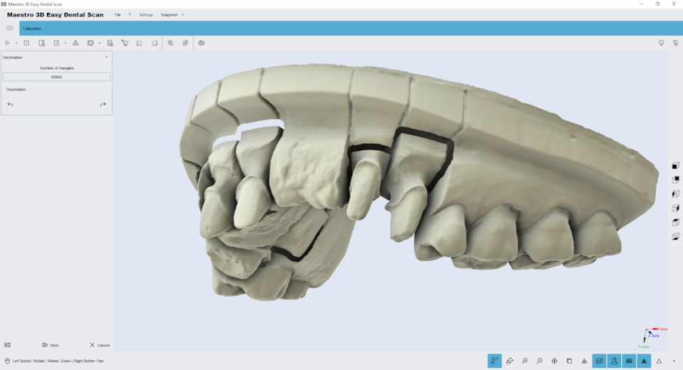
we can see that even at low resolutions as shown in the image below, of about 80,000 triangles the quality of the 3D model is still appreciable.
3D Comparison
To perform the model comparison it is possible to select the "reference" model and the "test" model. The following image shows the 3D comparison performed on two different scans of the same model. As can be appreciated from the color map, the two models are practically identical.
|
TIP: before comparing two models it is necessary that they are aligned one on the other, through for example the function of #Manual_3-2-1_alignment. |
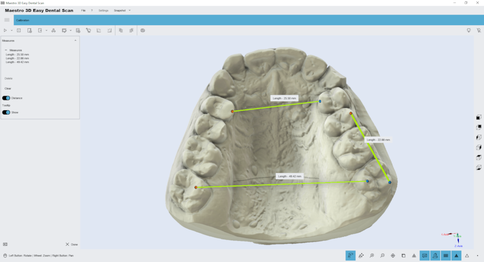
Free Measures
In order to perform the measures of length or angles, select the item to inspect and then goto in measures feature.
|
TIPS: double-click with left mouse button to add a point. |
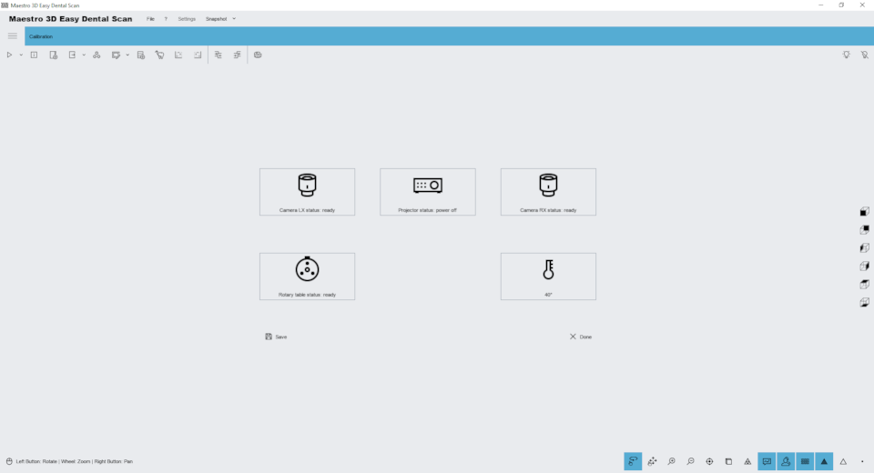
Scanner Status
Through this function, you can monitor the status of the scanner hardware. The window will show the status of each hardware device inside the scanner.
Dental Studio - Ortho Studio module Wizard
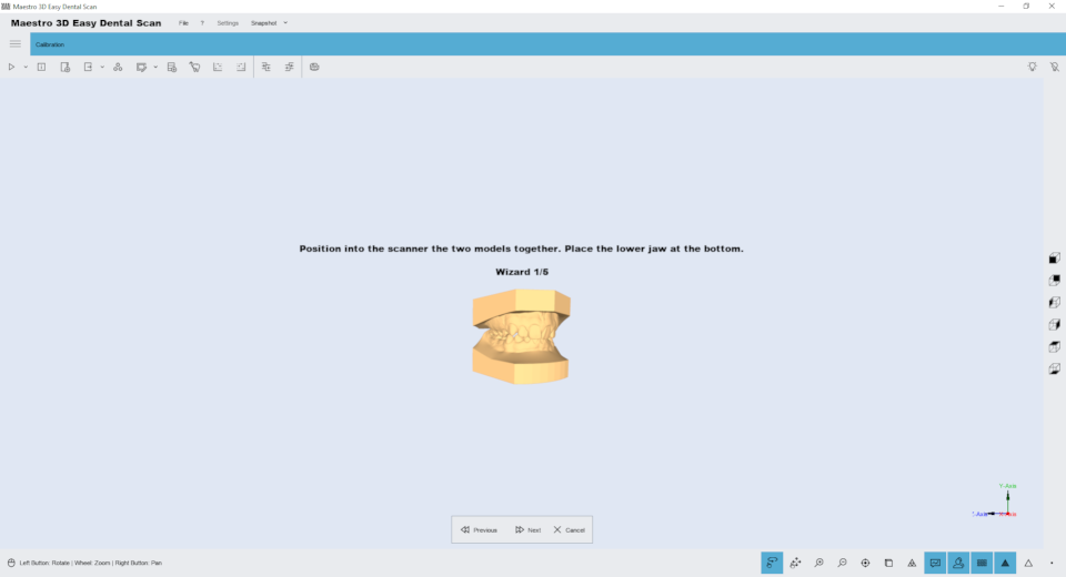
This scanning wizard helps the user to make all necessary scans and alignments to obtain a complete case to work into Dental Studio software - Ortho Studio module.
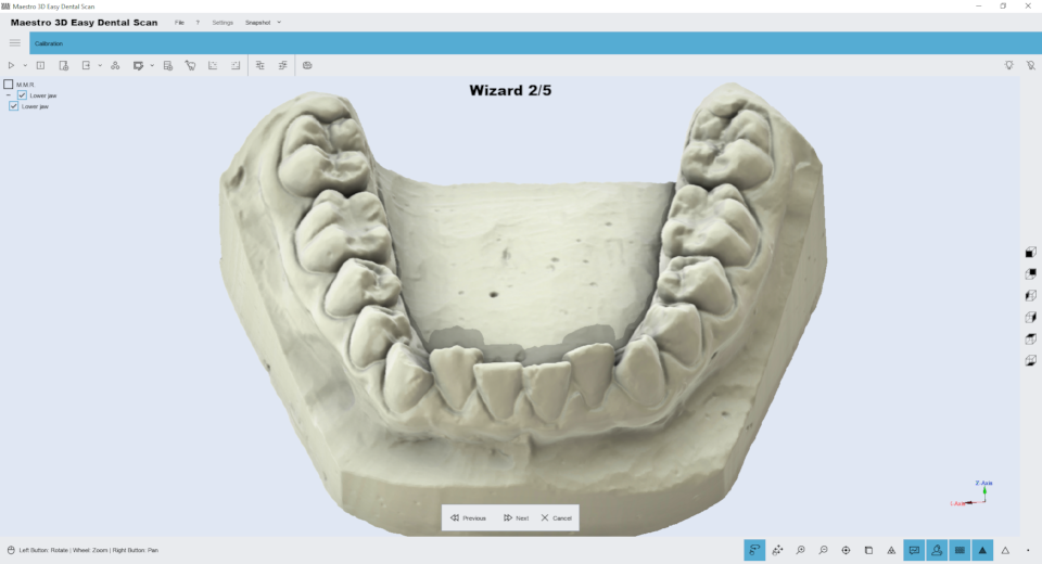
The following image shows the first step of the scan. In this phase you can scan maxillary and mandibular relationship. In this window you can change the scanning settings and the scanning strategy.
The following image shows the result of the maxillary and mandibular relationship. Now the user can scan the lower arch.
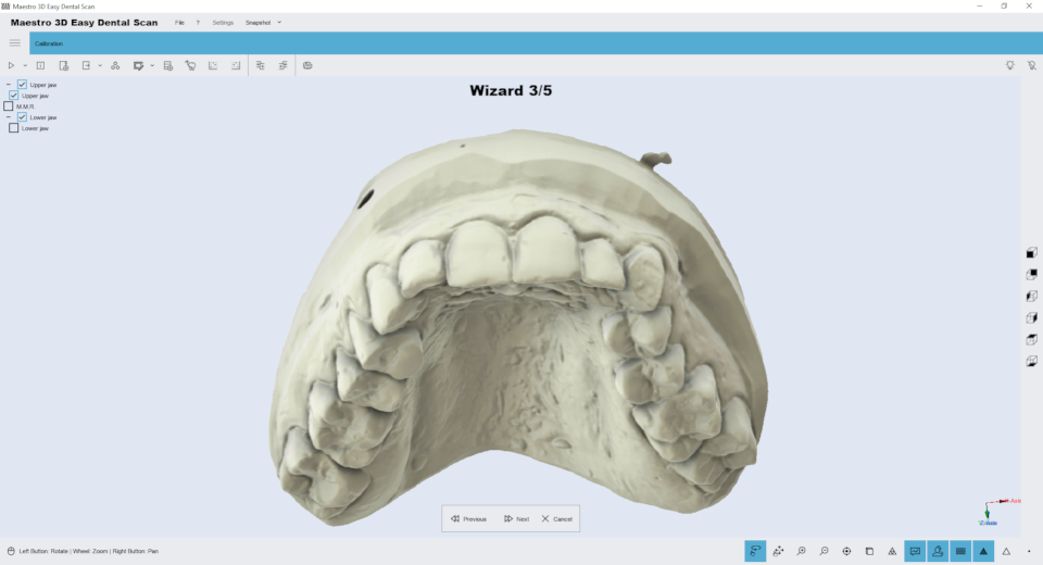
The following image shows the result of the lower arch. Now the user can scan the upper arch.
The following image shows the result of the upper arch. Now it's possible to perform the alignment of the upper and lower arch respect to the relationship. The procedure of alignment is the Manual 3 2 1 Alignment.
After that the scanning software send the correct data to the Ortho Studio software.
Dental Restoration Wizard
This scanning wizard helps the user to make all necessary scans and alignments to obtain a complete case to work into all dental cad integrated with Maestro 3D Scanner. All Maestro 3D scanners are fully integrated with leading design software such as exocad and Maestro_3D_Dental_Studio_-_User_Manual#Dental_restoration_.2F_Dental_CAD. The following image shows an example of a wizard step of the scan. In this window you can change the scanning settings and the scanning strategy.
Exocad Wizard
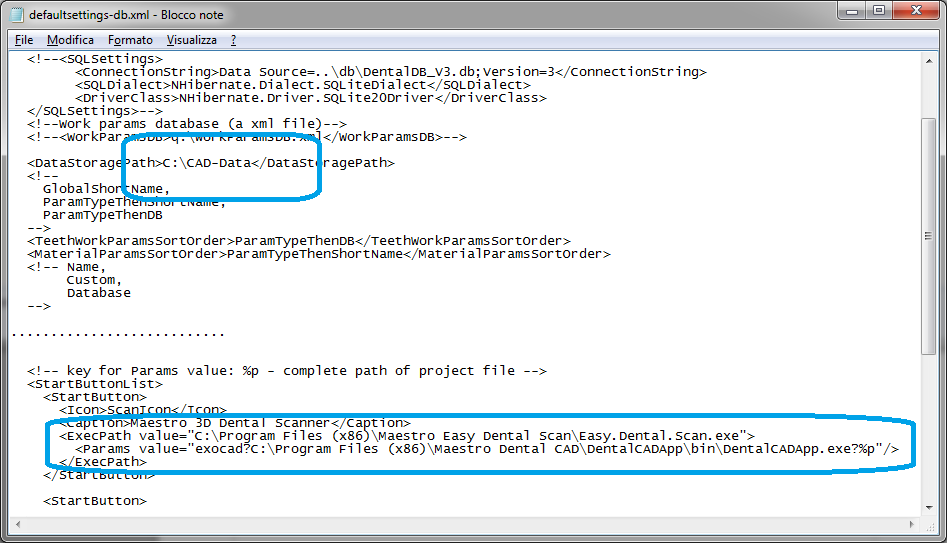
To integrate the scanner with the exocad software you need to edit the file \exocad-folder-installation\DentalDB\config\defaultsettings-db.xml as shown in the figure below.
<DataStoragePath>C:\CAD-Data</DataStoragePath>
...
<StartButtons>
<Button>
<Icon>ScanIcon</Icon>
< caption > Maestro 3D Dental Scanner < /caption >
<ExecPath value="C:\Program Files\Maestro Easy Dental Scan\Easy.Dental.Scan.exe">
<Params value="exocad?C:\Program Files\exoCAD\DentalCADApp\bin\DentalCADApp.exe?%p"/>
</ExecPath>
</Button>
...
- <ExecPath value = is the path where you have installed the Easy Dental Scan.
- <Params value = is the string exocad? and the path where you have installed dentalCADApp with ?%p at the end of the string.
Calibration
Calibrate a scanner model that is earlier than MDS500
Calibrate the MDS500
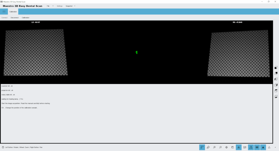
Click on the tab Calibration, place the calibration sample in the scanner and press the button Connect and once the images of the two cameras appear as shown above, press the button Calibration.
The calibration process is totally automatic, during this operation the optics, the motors and the relative axes are calibrated. Wait until a successful or error message appears on the screen. After this you can remove the calibration sample, store it and continue with the scans.
The calibration process takes a few minutes. It is advisable to keep the door closed during the calibration process and not to hit the table where the scanner is housed.
What is calibration?
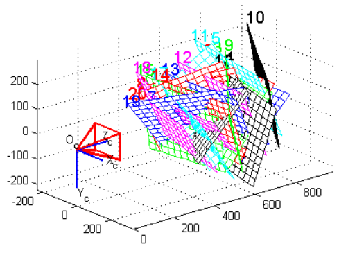
In a 3D scan system, calibrate a camera means extract the position of the ground plane in the chosen reference and a serial of parameters, necessary to the following elaboration. These parameters are called intrinsics and they are:
- focal length (fo)
- image center (cc)
- radial distortion factor (k)
As told before, the goal of the camera calibration is to estimate the intrinsics parameters (focal length, image center and radial distortion factor) and to identify the position of the ground plane in the solidal reference with the camera.
Cameras calibration is a basic procedure to extract metric piece of information from 2D images. A camera is usually represented by the central projector model pinhole camera. This model is defined by two parameters:
- Intrinsic parameters (from three to five): they describe the camera independently from their position in the space.
- Extrinsic parameters (six): they describe camera position in the space, independently from their internal features.
This model must be conveniently correct to consider optical distortions introduced by camera lenses. The use of this kind of lenses, introduces a distortion which is necessary to balance before making a whatever calculation.
In literature there are several models to describe this kind of phenomenon. The model which has been studied and developed by Maestro 3D, estimates the lenses distortions in order to obtain a calibration which allows an excellent attention in the scanning process.
To calibrate a camera we could use the following way: focus on a chessboard whose dimensions are known, which is situated on the ground plane. From its examination, it is possible to obtain all the necessary piece of information.
How can I understand if my Scanner is not calibrated?
The main indicators of a non calibrated Scanner are clear disalignments on the surface, in the scanning process result.
In case of a bad calibration of the Scanner, it could be possible to see an error message of this type The object has moved during the Scanning process.
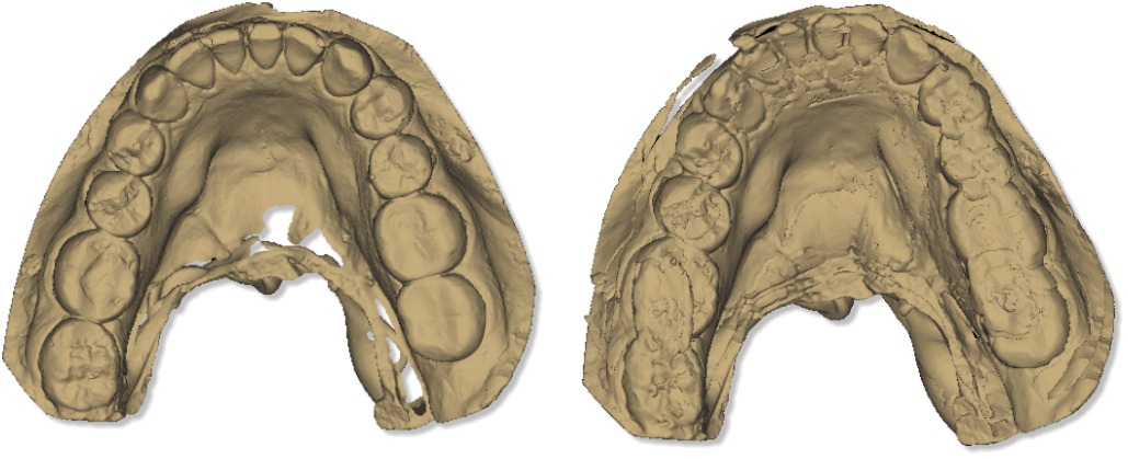
The picture here below, shows the same object, on the left we have a scan with a Scanner perfectly calibrated, while on the right a scan with a Scanner non-calibrated.
How many times it is necessary to calibrate the Scanner?
The quality of the materials and the solidity of the structure permit not to calibrate very often the Scanner if it has used correctly.
Nevertheless, excessive jump in the temperature or bad hits, could damage the machine and make the calibration necessary.
Small disalignments and imperfect calibrations are not evident on the final result, for this reason it is recommended to make the Scanner calibration every 1 month.
FAQ
How can I see the Software version and the scanner serial number?
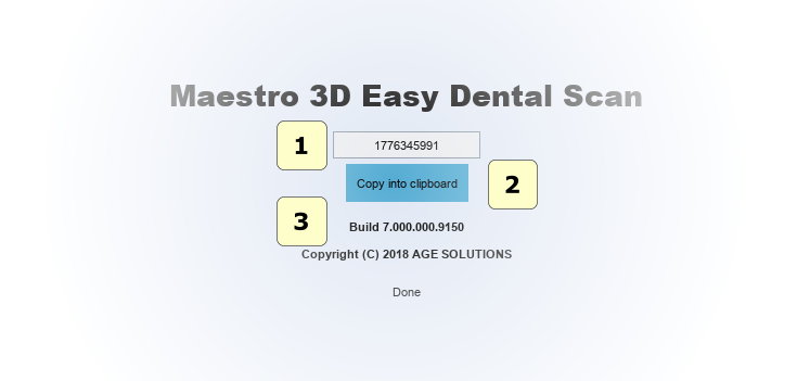
From the menu of the main window, tap on the enter ? -> About.... The image below shows the About window of the Software. In this window there is the scanner serial number, (tap on the bottom to copy it in the clipboard) and the version number Build
- 1) Scanner serial number.
- 2) Copy scanner serial number into clipboard.
- 3) Software Build Release version.
How can I see if my Software version is updated to the last available?
From the main menu tap on the entry File -> Check for updates.
How can I know which modules are active?
From the main menu tap on the entry File and tap on the entry Activate for each available module. Here, a message that will show if the module is active will appear; otherwise a window to import the license file that will activate the module in case it is not, will open.
How can I make a backup of all the scans?
Just make a copy of the folder where the software saves all scans. By default the folder is c:\MaestroData\.
The software is very slow on startup, what can I do?
If the software is very slow on startup, the cause is probably that the save folder (by default c:\MaestroData\) contains many scans. Just empty the folder or delete it completely and restart the software.
How can I access the program settings?
Through the appropriate button shown in the figure you can access the settings screen.
With this screen you can change, language, skins, colors, display settings, scan settings and much more.
Photorealistic Rendering is very slow, how can I disable it?
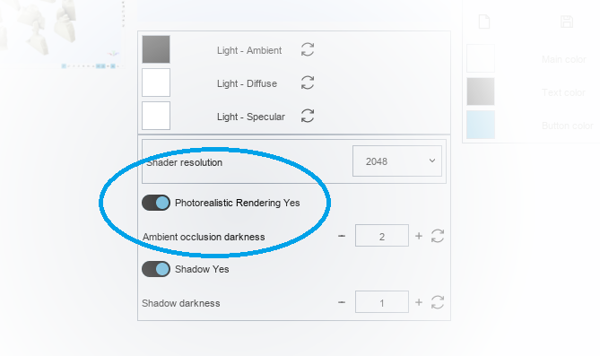
Photorealistic rendering requires high performance video cards. We recommend using NVIDIA video cards, GeForce family, 10 GTX series or better with 2 GB RAM or more. To temporarily disable photorealistic rendering, press the appropriate button in the bottom toolbar as shown in the figure:
If you want to disable by default each time the software is started, it is advisable to disable it in the settings screen:
#How_can_I_access_the_program_settings.3F
Here you can disable photorealistic rendering:
How can I change the save folder?
Edit the file application.settings.xml which is located in the installation folder of the software and change the string MaestroFolderData="c://MaestroData". To restore the settings with default value, just delete the file application.settings.xml and restart the software.
Metal parts can be scanned?
Yes it's possible but in order to improve scanning of metal parts you must use a scanning spray. In the market there are a lot spray but we advise the [Vacalon quickcheck spray].
Why is the Maestro 3D scanner closed inside a chassis and not open like many others?
The choice to keep the scanner closed in a special chassis instead of leaving it completely open as is the current trend, is a choice dictated by our company philosophy. Maestro 3D follows a path of technological growth in which the goal is to obtain the best possible results, in terms of accuracy, precision, resolution and repeatability of the scanned 3D models.
The technology on which the Maestro 3D system is based is an advanced variant of structured light. This technology consists in projecting special light fringes on the object to be scanned. The cameras acquire hundreds of images in which the algorithms identify the passage of the luminous fringe from white to black. In other words, you should look for the edge of every single luminous fringe.
To do this and identify these edges with sub-pixel precision, a very high light contrast between white and black is needed. It is quite evident that having a scanner without a chassis, completely open, drastically reduces this contrast. Ambient light affects heavily reducing the contrast of the projected light. Less contrast means lower levels of accuracy and precision.
For this reason, Maestro 3D has decided to pursue the choice to enclose and protect the scanner from a closed chassis in order to eliminate any influence of ambient light.
Are the cameras in the scanner in color or are they monochrome? And why?
The cameras are monochromatic. This is because the algorithms that work with structured light or variants of this, must look the edge of each single light fringe. This is why we need a very high contrast between white and black. The grayscale image is obviously perfect for this purpose.
Working with color cameras would not help this recognition but would reduce the information held by the algorithm. This is because in the color cameras takes up space in the sensor to represent every single pixel with 3 channels (R,G,B), (Red, Green, Blue). With monochromatic cameras the same space is occupied only by the representation of the gray scale.
As the grayscale image is required to detect the edges of the light fringes, the monochrome camera collects much more useful data for the scanning process of a color camera.
If you decide to work with color cameras, it would still be necessary to convert the grayscale image via software to be able to scan. With the conversion you would lose a lot of information, obtaining a much less detailed grayscale image of the same grayscale image obtained from a camera with a native monochromatic sensor.
Why the Maestro 3D scanner is white light and not blue like many others?
The scanner cameras are monochrome in grayscale, therefore, the only effect that brings blue light is a lower contrast of the image.
By projecting white light the RGB channels of the projector sensor are used 100% because the white is obtained with (R=100%, G=100%, B=100%), this allows you to have high brightness and high contrast.
Using blue light or variations of it, the sensor channels of the projector are not used at 100%, example (R=0%, G=50%, B=100%). The only result obtained is a lower brightness and a lower contrast.
If the goal to be pursued is the highest precision, accuracy, resolution of a 3D scan, white light is better than blue light.
If the goal to be pursued is the effect on the audience and the scenography, blue light is probably better than white light.
