Maestro 3D Dental Studio V6 - User Manual
Video Tutorials
Recommended PC hardware configuration
Processor: the clock rate of CPU is very important, at least 3.7 Ghz, our software fully exploiting the parallel calculation offered by the multicore and multithreading technologies, for this reason, you can also use a quad-core. We will recommend the following product line:
- Intel® Core™ i7, i9 - 4 GHz
Ram: 16-32 GB
Graphic card: Nvidia GeForce GTX/RTX Series, with 2 GB
USB 3.0
OS: Microsoft Windows 10/11 - 64 Bit
Monitor: full HD 1920x1080
Specification Sheet
| Combined with third party scanners | |
| Intraoral scanner ready | |
| Input Files | STL, PLY, OBJ
|
| Management of the actual color of the scan | |
| 3D Face ready | |
| Study Models | ABO, ABO 2013, Ricketts, Parallel, Tweed
|
| 3D Label | |
| 3D Modeling tools | |
| Brackets removal tools | |
| 3D Measuring tools | |
| 2D Image support | |
| Alignment of 2D images and 3D model | |
| Occlusion map | |
| Automatic teeth segmentation | |
| Automatic teeth axis, FA, Tip, Torque calculation | |
| Virtual roots | |
| Virtual setup | |
| IPR, stripping | |
| Multiple virtual setup projects | |
| Real-Time collision detection (automatic intersection, distance, calculation) | |
| Attachments placement | |
| Customizable attachments | |
| Attachments designer | |
| Brackets placement | |
| Brackets designer | |
| Brackets JIG support | |
| Automatic transition models constructions | |
| Automatic 3D label on transition models | |
| Automatic adaptation of virtual pontic on transition models | |
| Automatic template models generation | |
| Cut and Close | |
| Bite Creator | |
| PDF report | |
| Video recording | |
| Automatic Video report | |
| Cloud integration | |
| Clear aligners for transition models | |
| Etching guide for attachment placement | |
| Clear aligners for brackets placement | |
| Output files | STL, PLY, OBJ, ZIP-STL, ZIP-PLY, ZIP-OBJ
|
| Annual fees | |
| Compulsory updates | |
| 3D mouse, touchscreen ready | |
| Operation system | Windows 10, 64 bit
|
| Video tutorials | |
| Wiki user manual |
Software Installation
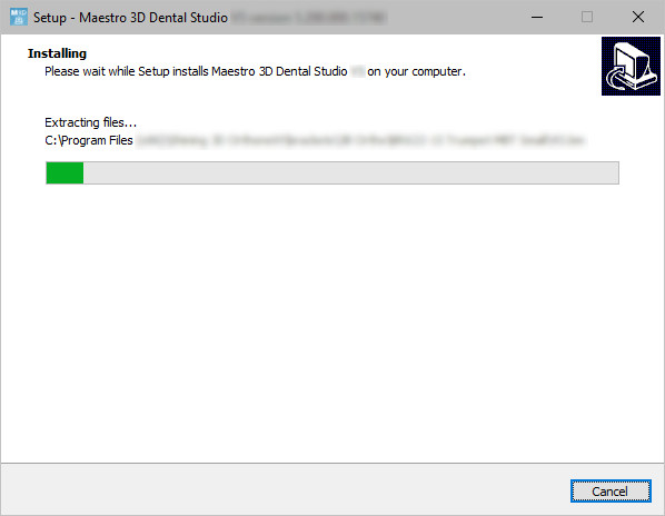
To install the software, run the installation file with administrator rights. In the various phases of the installation process, it will be possible to choose the destination folder, whether or not to add an icon to our desktop, etc. See the image below which shows an installation step.
This operation takes a few minutes. At the end of the operation, the installation will have created two icons on the desktop ![]()
- Maestro 3D Dental Studio the CAD application;
- Maestro 3D Dental Studio Order Management the software for managing the customer database and creating a new case and opening an existing one.
First activation of the license
Before starting check:
- to have an Internet connection;
- to have added to the exceptions list of your firewall and antivirus the executable software Dental.Studio.exe and Dental.Studio.Order.Management.exe;
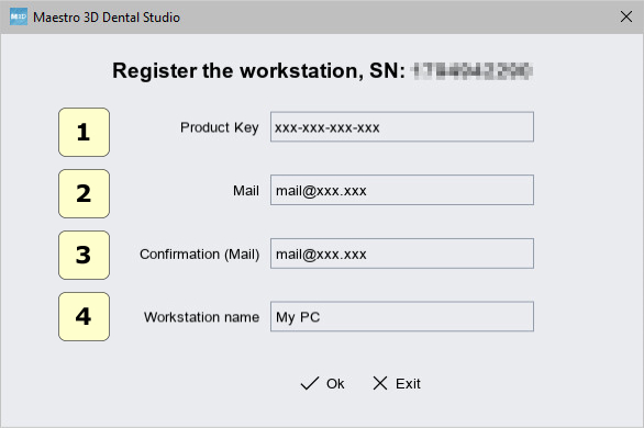
At the first run the software will show a window like this:
- 1 write the product code assigned and unique for your license;
- 2 write your email to receive confirmation of the activation;
- 3repeat your email;
- 4 write the name you prefer for the workstation;
Press Ok to activate the license.
Important notes on the license
The activation procedure, described above, activates the license on the workstation.
It is necessary to repeat the activation procedure each time the workstation is modified or changed. For this reason, it is recommended to keep the product code.
The maximum number of workstations that can be activated is 5. However, the license cannot work simultaneously in more than one workstation.
The license, after the first activation, can work offline. The workstation may therefore not be connected to the Internet.
Only for the first activation, it is necessary to use an Internet connection.
However, we recommend using the software on a workstation connected to the Internet to check for software updates or if you want to use the cloud interface.
Order Management
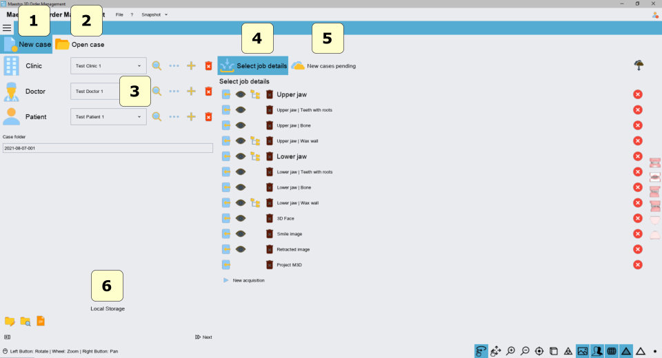
The Order Management application allows you to manage work cases.
- database management of clinics, doctors and patients and cases associated with patients;
- creating a new work case, importing files from disk, from cloud, or directly interfacing with the Maestro 3D scanner;
- opening of existing work cases;
- 1 Tab new case;
- 2 Tab open case;
- 3 Clinic, doctor and patient management;
- 4 Input file for the case.
- 5 Tab new pending case coming from cloud;
- 6 Tools to change local storage folder and backup all data.
|
TIP: make periodic backups of the work case folder. |
Create a new (local) work case
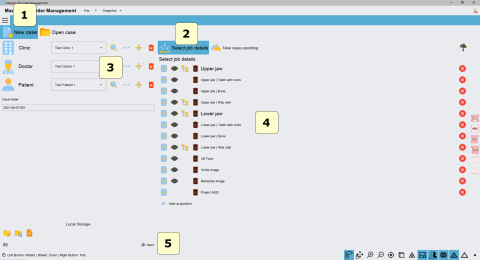
Per creare un nuovo caso di lavoro:
- select tab 1 of the new cases;
- select tab 2 of the input file;
- select clinic, doctor and patient, 3;
- upload the input files, 4;
- press 5;
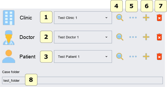
Clinic, doctor and patient management
- 1 List of clinics;
- 2 List of doctors;
- 3 List of patients;
- 4 Search. By entering a textual value (for example part of the name or surname), the relative drop-down menu will be populated only by the elements that respect the search criteria;
- 5 Edit. A tab will appear through which it will be possible to change the data of the selected item;
- 6 Add. A tab will appear through which it will be possible to enter the values of the registry;
- 7 Delete. Delete the currently selected item in the list;
- 8 Work case save folder;
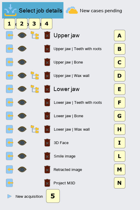
Input file to create a new work case
- 1 Upload input file from disk;
- 2 Display a preview of the uploaded file;
- 3 Select the file from the list of scans (only if you have a Maestro 3D scanner);
- 4 Delete the input file loaded;
- 5 Start a new scan (only if you have a Maestro 3D scanner);
- A Upper model;
- B Upper model of crowns and roots obtained from the segmentation process of a file from CBCT. This will be used to combine the scanned crowns with the real roots;
- C Upper model of the bony part (maxilla);
- D Upper model of the wax wall;
- E Lower model;
- F Lower model of crowns and roots obtained from the segmentation process of a file from CBCT. This will be used to combine the scanned crowns with the real roots;
- G Lower model of the bony part (mandible);
- H Lower model of the wax wall;
- I 3D model of the face scan;
- L Face image (smile);
- M Face image (retracted);
- N Project file *.m3d;
To achieve a work case, at least one arch (upper or lower) must be loaded.
Create a new work case (by importing a pending case from the cloud)
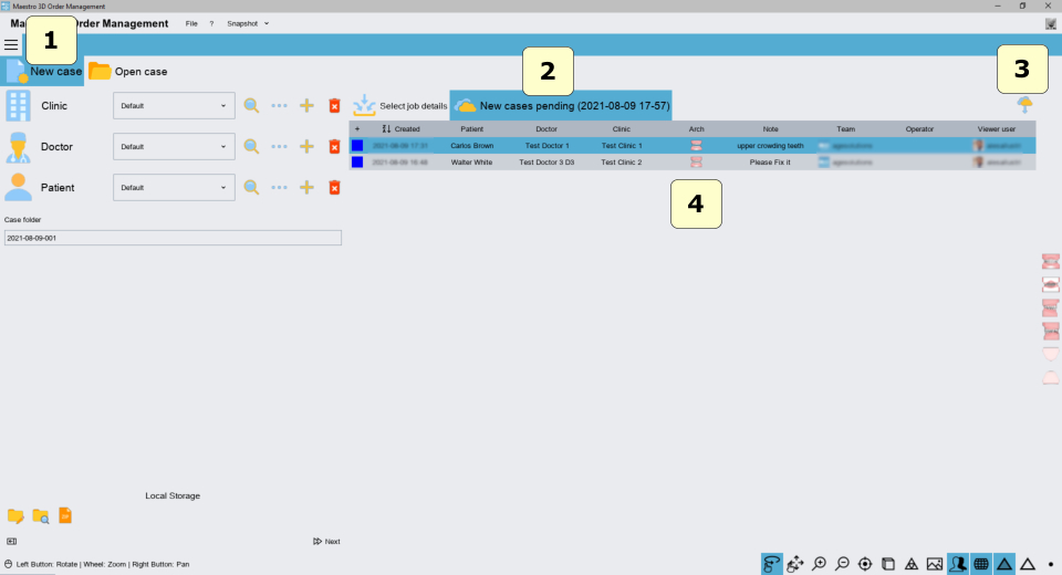
Pending cases are new work cases to process that have been uploaded to the cloud by a viewer user who is part of the workgroup via the cloud platform. The user of the viewer through the cloud platform enters the data of the patient, doctor, clinic and input files and waits for their processing.
- 1 Tab new case;
- 2 Tab new pending case coming from cloud;
- 3 Download the updated list of pending cases from the Cloud;
- 4 Table of pending cases;
To create a new work case starting from a pending case on the cloud, right-click on the selected case, activate the context menu and select the item1;
After the import phase and the download of the input files, the areas relating to the clinic, doctor and patient and the input files of the initial screen will be populated.
To start the new case press the Next button.
Open an existing (local) work case
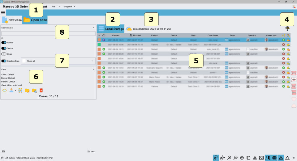
- 1 Tab open case;
- 2 Tab open local case;
- 3 Tab open cloud cases;
- 4 Download the updated list of work cases from the Cloud;
- 5 List of work cases;
- 6 Information and tools related to the selected work case;
- 7 Drop-down menu to display the list of cases according to a time span, (cases of today, yesterday, one-month-old, ...);
- 8 Search. By entering a search string, only the work cases that meet those criteria will be displayed. The patient, doctor, or clinic item can be ticked if we want the research to have an effect on these 3 elements. For example, if we enter the name or part of a patient in the search string, all cases related to that patient will be displayed. To cancel the search, simply delete the search string and press the enter key on the keyboard;
To open an existing work case:
- Select Tab 1;
- Select Tab 2;
- Select the case from the table 5;
- Double click on the selected case;
The next image shows the preview of the selected case.
- 1* Summary of users associated with the case, (the workgroup, the current operator and the user of the viewer);
- 2* Option to open the case with write rights. This is only possible if the work case is not in use by some other user;
- 3 Option to close order management after opening the case;
|
* options enabled only if you have a cloud account; |
- 1 Preview of the currently selected work case;
- 2 Associate the currently selected work case with a different clinic\doctor\patient;
- 3 Clones the currently selected work case case;
- 4 Change the name of the folder related to the currently selected work case;
- 5 Open the folder relating to the currently selected work case with the Windows file manager;
- 6 Delete the currently selected work case.
All these tools mentioned above are also accessible via the context menu of the work case.
Case table
- 1 Color map indicating the creation or modification date of the work case;
- 2* Work case status of the local copy and the cloud copy. Indicates if there is a more recent version of the work case locally or on the cloud;
- 3 Creation date;
- 4 Date of last modification;
- 5 Patient associated with the case;
- 6 Doctor associated with the case;
- 7 Clinic associated with the case;
- 8 Case folder;
- 9* Working group associated with the case;
- 10* Last operator of the working group who modified the case;
- 11* Viewer user associated with the case;
- 12* Sharing the case with the viewer user; Indicates whether sharing is on or off. When sharing is active the viewer user will have access to the work case;
- 13* Indicates whether the work case is in use by some user in the workgroup or not in use. When a work case is currently in use by some user, the case can be opened as read-only and changes are not allowed;
|
* options valid only if you have a cloud account; |
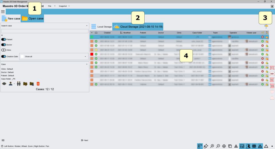
Open an existing work case (by importing it from the cloud)
- 1 Tab open case;
- 2 List of cases in the cloud;
- 3 Download the updated list of cases from the Cloud;
- 4 Case table;
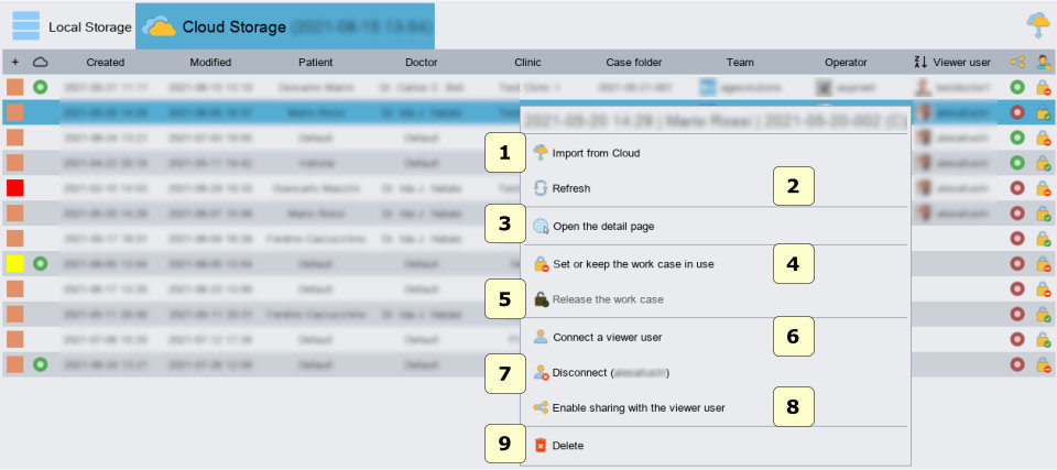
- 1 Import the case from the cloud;
- 2 Open the web page on the cloud portal;
- 3 Set the case "in use", this way other users will not be able to modify it;
- 4 Release the case, so other users can edit it;
- 5 Connect the case to a viewer user;
- 6 Disconnect the viewer user from the selected case;
- 7 Enable case sharing with the viewer user; Only after sharing is enabled, the user viewer will be able to view the case;
- 8 Delete the case from the cloud;
After importing the case from the cloud 1, the case will appear in the local case table.
Dental Studio User Interface
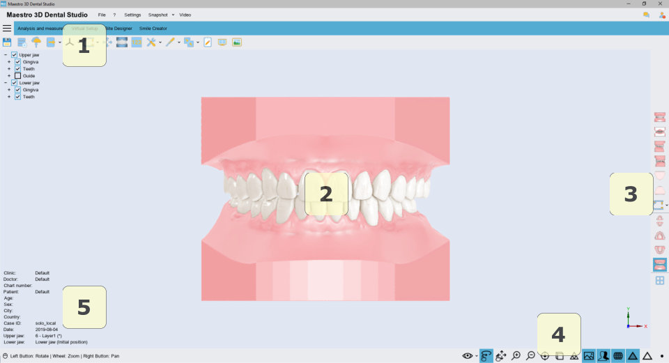
The image below shows how the software user interface appears.
- 1 Main Toolbar;
- 2 Display and work area;
- 3 Sidebar;
- 4 Display Toolbar;
- 5 Information area;
Main Toolbar
Home
- 1 File menu;
- check the updates;
- exit from the software;
- 2 Help menu;
- guide;
- displays information about the software version and the license;
- 3 Settings menu | change language, colors, display settings and autosave;
- 4 Capture screen menu;
- 5 Record a video menu;
- 6 Home tab;
- 7 Analysis and Measurements tab;
- 8 Virtual Setup tab;
- 9 Bite Designer tab;
- 10 Smile Creator tab;
- 11 Save project;
- 12 Close and return to Order Management;
- 13 Upload the case to the cloud;
- 14 Export;
- export study models;
- export M3D project for the viewer;
- 15 Reference system;
- 16 Change Articulation;
- 17 Change articulation freely;
- 18 Study models | virtual bases;
- 19 3D labels on the study models;
- 20 Repair 3D models | Removal of brackets from the input arches;
- 21 Modeling tool | add, remove material | smooth the surface;
- 22 Alignments; Align 3D face, wax wall, ..., 2D images with 3D model;
- 23 Note;
- 24 Multiple canonical views;
- 25 2D image collection;
Analysis and Measurements
- 1 Occlusal inspection;
- 2 4D Motion;
- 3 3D sections;
- 4 Mesio-distal measurements | Bolton analysis;
- 5 Measurement of the length of the arch;
- 6 Free measures | point-to-point | angles;
- 7 3D comparison;
Virtual Setup
- 1 Teeth segmentation;
- automatic segmentation;
- manual segmentation; single cutting line for each tooth;
- global cutting line;
- set tooth axes | center of rotation | FA point | initial Tip and Torque;
- Virtual Pontic;
- 2 Virtual Setup;
- virtual setup;
- Import new attachments;
- 3 Brackets positioning;
- brackets positioning;
- brackets library;
- 4 Construction of transition models;
- 5 Clear aligners;
- clear aligners;
- clear aligners for attachments positioning;
- clear aligners for brackets positioning;
- clear aligners (with window) for brackets positioning;
- clear aligners for brackets with jigs positioning;
- 6 Cut and close;
- cut and close with line;
- cut and close with plan;
- 7 3D labels on transition models;
- 8 Automated cutting of aligners;
- definition of the cutting lines;
- fixture positioning;
- 9 Drop-down menu of transition models for the upper and lower arch;
- 10 Treatment animation and speed control;
- 11 PDF report;
- 12 Video report;
- 13 Export;
- export clear aligners;
- export guide templates for attachments;
- export clear aligners for brackets positioning;
- export clear aligners (with window) for brackets positioning;
- export clear aligners for brackets with jigs positioning;
- export scanned model with the transfer keys for brackets;
- export transition models.
- 14 Upload to the cloud;
- upload 3D models for the webViewer;
- upload report of the treatment;
Bite Designer
- 1 Articolatore Virtuale;
- linea facciale occlusale;
- parametri dell'articolatore;
- 2 Rimozione dei sottosquadri;
- 3 Linea di taglio;
- 4 Crea bite;
- 5 Edita bite;
- 6 Esporta bite;
Smile Creator
- 1 Allinea immagini 2D e modello 3D;
- allinea immagine con divaricatore;
- allinea immagine del sorriso;
- 2 Ritaglia immagine;
- 3 Smile Creator 2D;
- Posizionamento 2D delle anatomie dei denti per il progetto del 3D Denture Guide;
- Posizionamento 2D delle anatomie dei denti per il progetto del Digital Mockup;
- 4 Definizione della cresta gengivale;
- 5 Smile Creator 3D;
- Posizionamento 3D delle anatomie dei denti per il progetto del 3D Denture Guide;
- Posizionamento 3D delle anatomie dei denti per il progetto del Digital Mockup;
- 6 Fusione booleana del mockup;
- 7 Creazione della placca per il progetto Digital Mockup;
- 8 Creazione del template per il progetto Digital Mockup;
- 9 Posizionamento del tripode per il progetto Digital Mockup;
- 10 Strumento di modellazione | aggiungi, rimuovi materiale | liscia la superficie;
- 11 Esporta;
Area di visualizzazione e di lavoro
L'area di visualizzazione e di lavoro è l'area della finestra dove i modelli 3D sono visualizzati e dove le operazioni di modifica sono consentite. Nell'area di visualizzazione è possibile visualizzare / creare le basi virtuali, visualizzare l'occlusione fra la mascella e la mandibola, visualizzare le misure dei denti, la lunghezza dell'arco e realizzare e mostrare il setup virtuale e tutte le altre fasi del lavoro.
Per esaminare i modelli visualizzati, i parametri della camera (posizione, scalatura, rotazione) possono essere settati attraverso uno strumento chiamato trackball. La trackball è uno strumento semplice da utilizzare per muovere ed interagire con la scena 3D.
- Premere e trascinare il tasto sinistro del mouse per ruotare intorno al modello;
- Ruotare la rotella centrale del mouse per effettuare lo zoom;
- Premere il tasto centrale del mouse o la rotella per cambiare il centro di rotazione della scena 3D;
- Premere e trascinare il tasto destro per muovere la camera.
Barra laterale
|
Barra degli strumenti di visualizzazione
- 1 Mostra\Nascondi e cambia la trasparenza dei componenti della scena 3D;
- 2 Abilita la modalità ruota o trascina per il touchscreen;
- 3 Ingrandisce [tasto PGDown] / rimpicciolisce [tasto PGUp] la scena 3D;
- 4 Resetta la vista;
- 5 Cambia la proiezione della camera che inquadra la scena 3D: proiezione parallela [tasto O], proiezione prospettica [tasto P];
- 6 Cambia le proprietà di illuminazione dei modelli 3D: smooth shading [tasto S], flat shading [tasto F];
- 7 Abilita fotorealismo;
- 8 Abilita le ombre (solo se il fotorealismo è attivo);
- 9 Visualizza / nasconde il colore reale dei modelli 3D, se il colore reale è stato acquisito durante la scansione;
- 10 Visualizza / nasconde i triangoli;
- 11 Visualizza / nasconde i bordi dei triangoli [tasto E];
- 12 Visualizza / nasconde i punti [tasto V].
Area informativa
L'area informativa che si trova nell'angolo in basso a sinistra della schermata principale, racchiude tutte le informazioni principali del caso del lavoro. Ad esempio è riportato il nome della clinica, del dottore, i dati relativi al paziente, l'identificativo del caso di lavoro e i modelli correntemente visualizzati.
Impostazioni
Come mostrato in figura, premere sulla voce di menù 1:
Il software mostrerà una schermata come quella mostrata nella figura sottostante:
- 1 Autosalvataggio;
- 2 Cambia lingua dell'interfaccia;
- 3 Numerazione (Internazionale, Americana);
- 4 Modalità di cattura schermo;
- 5 Dimensione testo e icone;
- 6 Impostazioni di rendering;
- 7 Colore di sfondo;
- 8 Immagine di sfondo;
- 9 Combinazione di colori dell'interfaccia utente.
FAQ
Come posso vedere la versione del software? I moduli attivi? Il seriale della licenza?
Come mostrato in figura, attivare il menù 1 e premere 2.
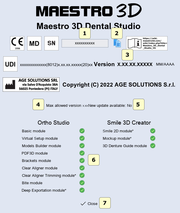
Il software mostrerà una schermata come quella mostrata nella figura sottostante:
- 1 Seriale della licenza;
- 2 Copia il seriale della licenza negli appunti;
- 3 Numero di versione del software;
- 4 Massima versione disponibile a cui è possibile aggiornare la licenza;
- 5 Mostra se sono disponibili nuovi aggiornamenti;
- 6 Per tutti i moduli presenti nella versione del software vengono mostrati quelli attivi e quelli non attivi;
- 7 Chiude la schermata.
Come posso vedere il codice prodotto della licenza?
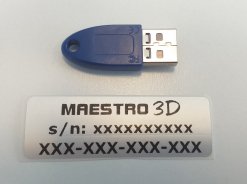
Il codice prodotto è un codice composto da 12 numeri con il seguente formato XXX-XXX-XXX-XXX.
Tale codice è stato fornito al possessore della licenza tramite mail in fase di acquisto e/o lo si può trovare scritto su di un etichetta incollata alla scatola che contiene la dongle usb. Si veda l'immagine sotto.
Questo codice è necessario per effettuare la prima attivazione del software su di un nuovo PC.
Si consiglia di conservare questo codice, in quanto può essere necessario per installare un nuovo aggiornamento del software o nuovi moduli.
Come posso sapere se la mia versione del software è aggiornata all'ultima disponibile?
Come mostrato in figura, attivare il menù 1 e premere 2.
Un messaggio mostrerà se sono presenti o meno aggiornamenti.
Che caratteristiche devono avere i modelli di input?
I modelli di input devono essere file STL\PLY\OBJ registrati nella corretta occlusione;
- Non devono contenere tunnel;
- Non devono contenere maniglie;
- Devono essere manifold;
- Non devono avere buchi;
- Non devono avere triangoli degeneri (esempio triangoli con zero area);
- Non devono avere triangoli duplicati;
- Non devono avere vertici non riferiti;
- I triangoli devono avere tutti lo stesso orientamento;
|
CONSIGLIO: Utilizzando lo scanner Maestro 3D si ha la garanzia che i modelli di input siano perfettamente conformi alle richieste del software senza dover utilizzare programmi di terze parti per riparare i modelli. |
Come posso cambiare la lingua del software?
Come mostrato in figura, premere sulla voce di menù 1:
Come posso fare un backup di tutti i casi di lavoro?
- 6 Strumenti per cambiare la cartella di archiviazione locale e fare un backup di tutti i dati;
- 1 Cambia cartella di archiviazione;
- 2 Apri cartella con Esplora risorse di Windows;
- 3 Backup della cartella; Crea un file zip con tutta i casi di lavoro; Questa operazione potrebbe richiedere alcuni minuti, dipende dal numero di casi e dalla grandezza della cartella;
