Maestro 3D Ortho Studio - Manuale Utente
Introduzione all'utilizzo del software Maestro 3D Ortho Studio
Questo documento ha lo scopo di introdurre l'utente in modo semplice ed intuitivo all'uso del software Ortho Studio. Si prega di leggere attentamente il manuale prima di utilizzare il software.
Introduzione
Maestro 3D Ortho Studio è un software facile da utilizzare sia per i laboratori che per gli ortodonzisti.
Le principali caratteristiche sono:
- Gestione di una base di dati con Pazienti, Dottori e Cliniche.
- Scelta del sistema di riferimento per le due arcate.
- Creazione e modifica delle basi virtuali.
- Setup Virtuale.
- Ispezione occlusale.
- Analisi di distanze, misure e sezioni.
Installazione del Software
Per installare il software Maestro 3D Ortho Studio, fare doppio click sul file Maestro.3D.Ortho.Studio.vx.xx.xxx.Setup.exe
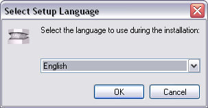
Step 1: Selezionare la lingua di installazione.
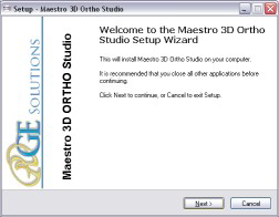
Step 2: Una finestra di benvenuto apparirà sullo schermo, premere Avanti per continuare.
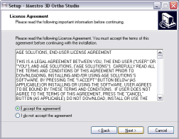
Step 3: Si prega di leggere attentamente la licenza d'uso del software. Accettare la licenze e premere Avanti per continuare.
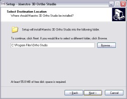
Step 4: Selezionare la cartella di destinazione. (Noi consigliamo di utilizzare la cartella di default). Premere Avanti per continuare.
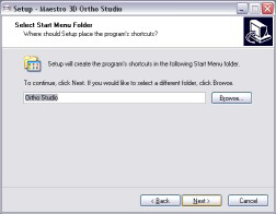
Step 5: Selezionare la cartella del menu Start. (Noi consigliamo di utilizzare la cartella di default). Premere Avanti per continuare.
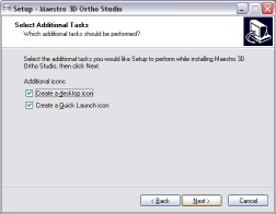
Step 6: Selezionare se desiderato di creare l'icona del programma sul Desktop. Premere Avanti per continuare.
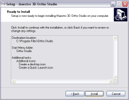
Step 7: A questo punto apparirà sullo schermo il riassunto di tutte le opzioni di installazione selezionate. Premere Installa per installare il software.
Una barra di progresso mostrerà l'avanzamento dell'installazione.
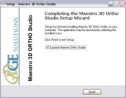
Step 8: Installazione completata. Premere Finire per completare.
| Utilizzare Windows 7 - 64 bit.
Installare tutti gli update di Windows disponibili. Installare gli ultimi driver disponibili dal sito di NVIDIA, web site http://www.nvidia.com. Impostare lo slider UAC (controllo account utente) al minimo. Tasto destro del mouse sopra l'icona del software e Proprietà -> Avanzate -> (spuntare) Esegui come Amministratore. |
Interfaccia Utente
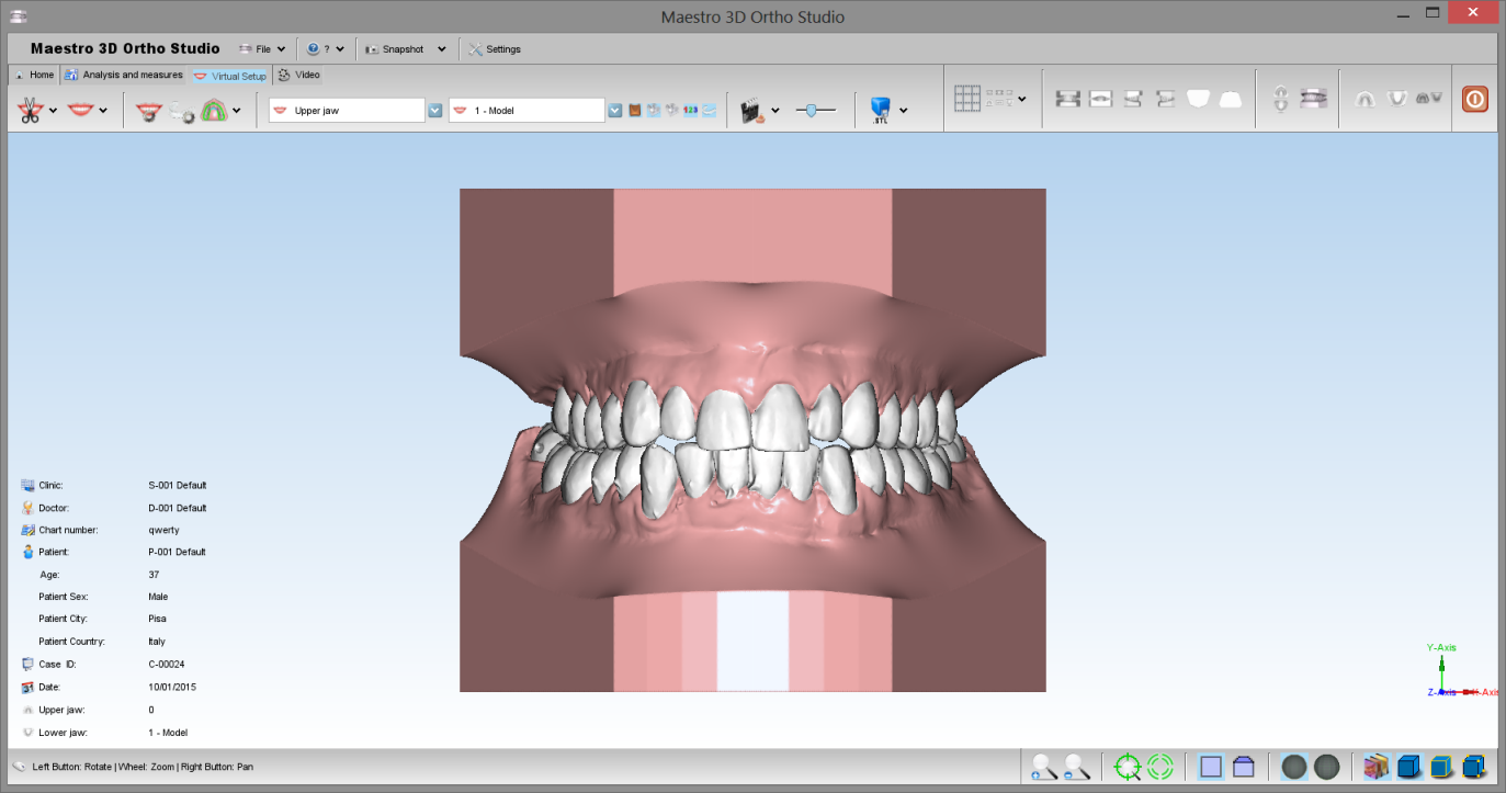
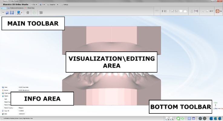
La figura sotto mostra come appare l'interfaccia utente del software.
Toolbar Principale
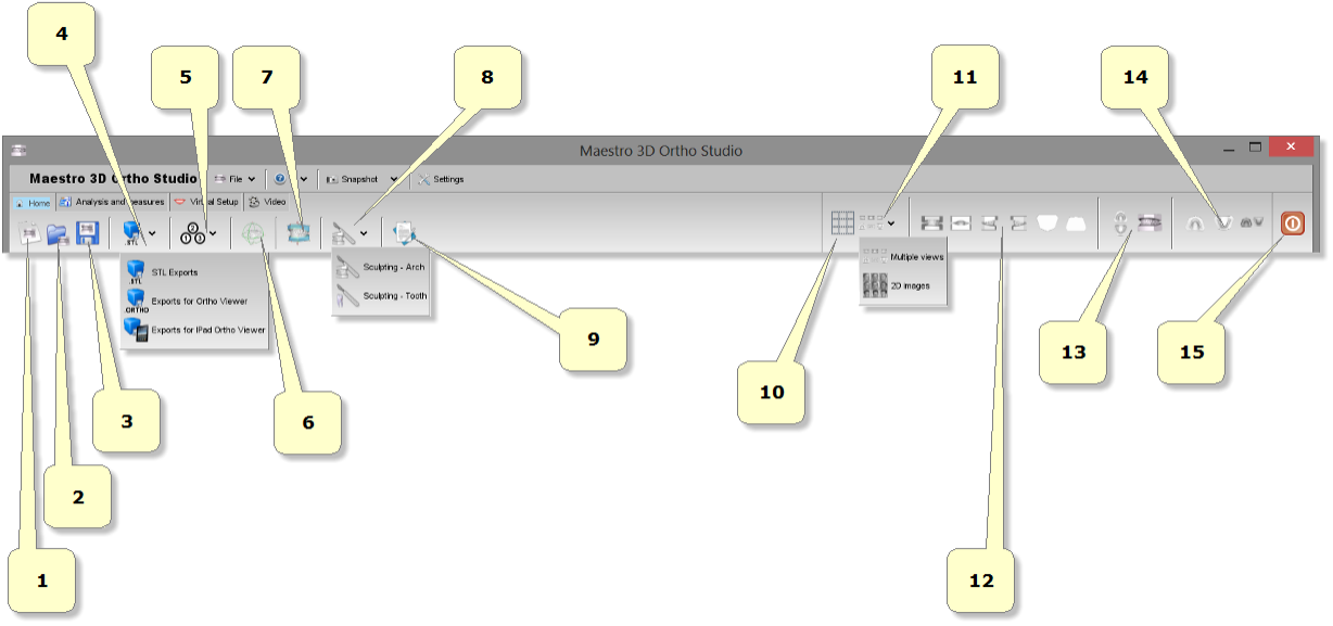
La toolbar principale permette di accedere a tutte le funzionalità dell'Ortho Studio Software.
- 1) nuovo caso.
- 2) apri un caso esistente.
- 3) salva caso corrente.
- 4) esporta:
- come Ortho: esporta il caso corrente in *.ortho file format. Utile per fare del digital service per i propri clienti. Con Ortho Studio Viewer i clienti possono vedere, ispezionare e misure i modelli ed anche il setup virtuale.
- come Orthoipad: esporta il caso corrente in *.orthoipad file format. Utile per fare del digital service per i propri clienti che hanno un Apple iPad. Con Ortho Studio Viewer iPad i clienti possono vedere ed ispezionare i modlli. Questa funzione di esportazione è accessibile solo se si utilizza uno scanner della linea Maestro insieme al software Ortho Studio. Scarica Ortho Studio Viewer per iPad qui: Ortho Studio Viewer iPad
- come Stl: esporta il caso corrente in una cartella. La cartella conterrà un file *.txt con le informazioni del caso e i modelli mascellari e mandibolari in *.Stl file format.
- 5) cambia sistema di riferimento.
- 6) cambia articolazione.
- 7) aggiungi basi virtuali.
- 8) Modellazione.
- 9) viste multiple.
- 10) viste:
- vista frontale.
- vista posteriore.
- vista lato destro.
- vista lato sinistro.
- vista superiore.
- vista inferiore.
- 11) apri/chiudi bocca.
- 12) visualizza mandibola/mascella/tutto. Cambiando la vista fra mascella o mandibola o entrambe si attivano\disattivano alcune funzionalità del software.
- 13) uscita.
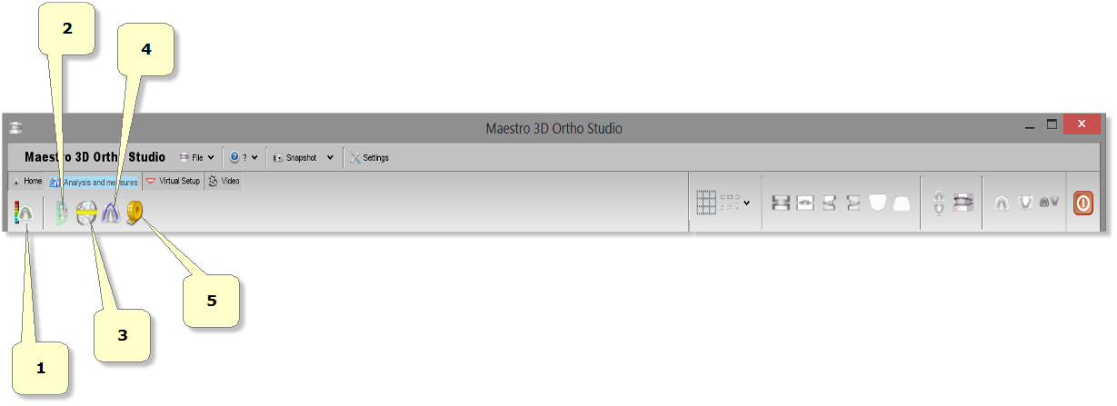
- 1) ispezione occlusale. Calcola le distance e i punti di contatto fra la mascella e la mandibola.
- 2) sezioni.
- 3) misure dei denti.
- 4) lunghezza dell'arcata.
- 5) misure libere:
- misure punto-punto.
- misure di angoli.
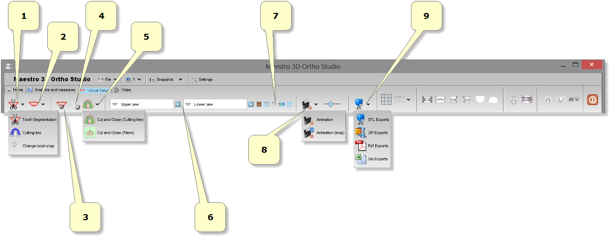
- 1) segmentazione:
- segmentazione dei denti: disegna una linea di margine per ogni dente.
- linea di taglio: separa i denti dalla gengiva.
- cambia sistema di riferimenti: aggiusta il sistema di riferimento e la radice per ogni dente.
- 2) setup virtuale.
- 3) costruzione dei modelli.
- 4) taglia e chiudi.
- 5) menu a tendina dei modelli mascellari e mandibolari.
- 6) mostra/nascondi attachi/brackets/brackets key/etichette.
- 7) animazione.
- 8) esporta:
- come file Stl.
- come file Zip.
Toolbar inferiore
La toolbar inferiore è l'area dello schermo che visualizza una barra di progresso durante ogni computazione e permette attraverso appositi pulsanti di cambiare le proprietà di visualizzazione.
- 1) ingrandisci [Key PGDown]/rimpicciolisci [Key PGUp].
- 2) mostra/nascondi trackball.
- 3) resetta trackball [Key R].
- 4) proieczione parallela [Key O], proieczione prospettica [Key P].
- 5) smooth shading [Key S], flat shading [Key F].
- 6) mostra/nascondi triangoli, bordi [Key E], vertici [Key V].
Area di Visualizzazione / Editing e Area di Informazione
L'area di visualizzazione ed editing è l'area della finestra dove i modelli sono disegnati e visualizzati e dove le operazioni di editing sono consentite.
Nell'area di visualizzazione è possibile visualizzare\creare le basi virtuali, l'occlusione fra la mascella e la mandibola, visualizzare le misure dei denti, la lunghezza dell'arco e realizzare e mostrare il setup virtuale.
Per esaminare i modelli visualizzati, i parametri della camera (posizione, scalatura, rotazione) possono essere settati attraverso uno strumento chiamato trackball.
La trackball è uno strumento semplice da utilizzare, Premere e trascinare il tasto sinistro per ruotare intorno al modello. Ruotare la rotellina centrare del mouse per effettuare lo zoom. Premere e trascinare il tasto destro per muovere la camera.
L'area di informazione è la parte dello schermo che mostra le informazioni sul caso, come il dottore, il paziente, l'identificativo del caso etc.
Creare un nuovo caso ed aprire un caso esistente
Creare un nuovo caso
Per creare un nuovo caso premere il pulsante![]() Nuovo Caso situato nella toolbar principale.
Nuovo Caso situato nella toolbar principale.
Il processo di creazione di un nuovo caso è composto dai seguenti passi:
- specificare la Clinica (opzionale).
- specificare il Dottore (opzionale).
- specificare il Paziente (opzionale).
- specificare la relazione fra Clinica, Dottore e Paziente (opzionale).
- sceglierei modelli mascellari e mandibolari (richiesto).
Per creare una nuova Clinica premere il pulsante ![]() Aggiungi nuova clinica, situato nella
sinistra dello schermo.
Aggiungi nuova clinica, situato nella
sinistra dello schermo.
Dopo aver completato la scheda specificando tutti i dati relativi alla clinica, premera il pulsante![]() Inserisci per aggiungere una Clinica al database o premere il pulsante
Inserisci per aggiungere una Clinica al database o premere il pulsante ![]() Pulisci per svuotare la scheda.
Pulisci per svuotare la scheda.
Nello stesso modo è possibile aggiungere un nuovo dottore, premendo il pulsante ![]() Aggiungi nuovo dottore. Per creare un nuovo paziente premere il pulsante
Aggiungi nuovo dottore. Per creare un nuovo paziente premere il pulsante ![]() Aggiungi nuovo paziente. Per definire un caso è necessario premere il pulsante
Aggiungi nuovo paziente. Per definire un caso è necessario premere il pulsante ![]() Seleziona paziente posizionato nella parte sinistra dello schermo.
Seleziona paziente posizionato nella parte sinistra dello schermo.
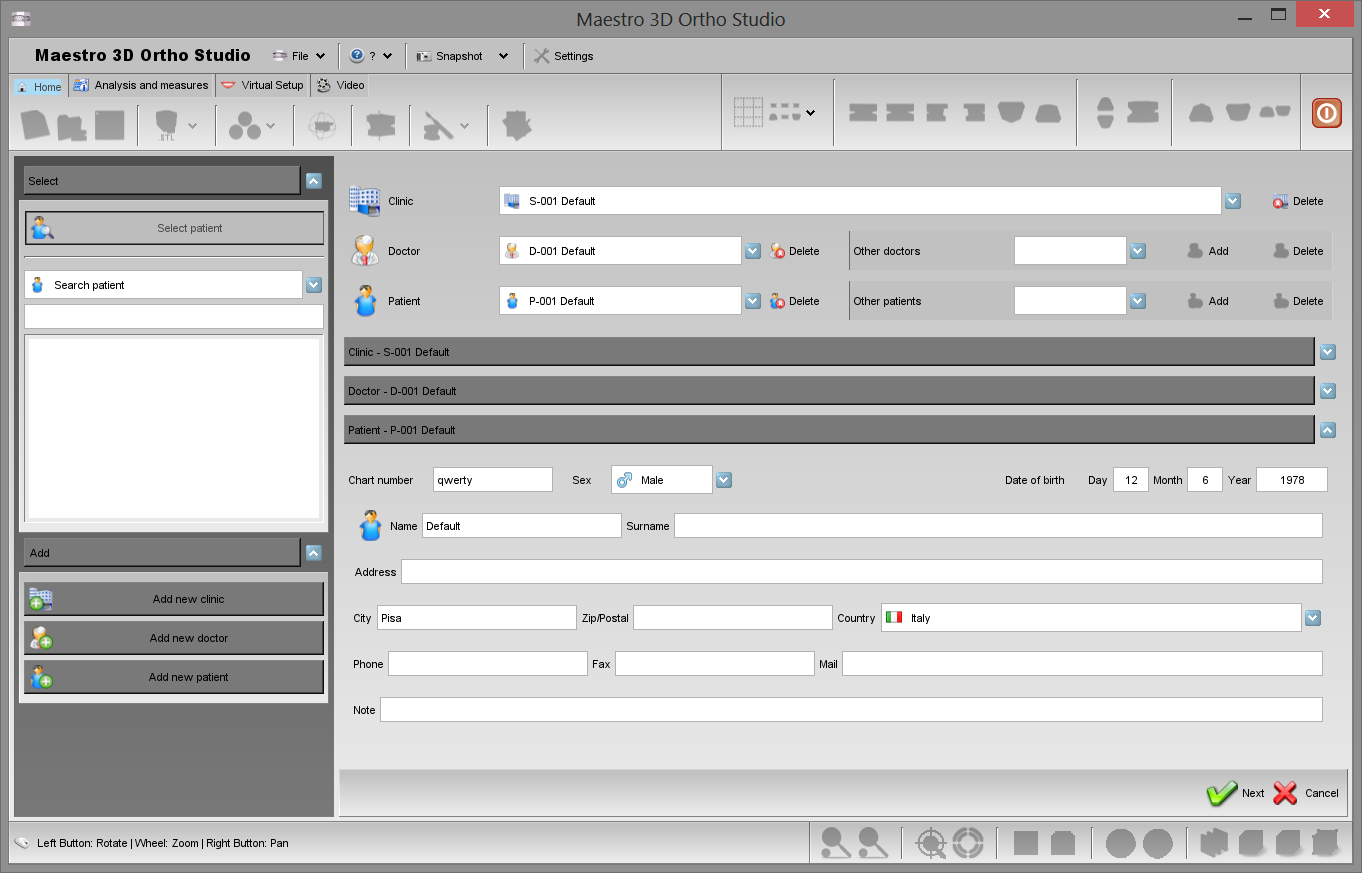
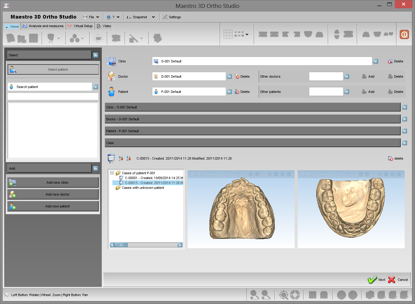
Nella parte principale dello schermo sarà possibile selezionare la relazione fra Clinica, Dottore e Paziente. (Si veda l'immagine sottostante).
Selezionare la clinica dal menù a tendina. Il pulsante ![]() Elimina consente di eliminare la clinica selezionata. Si prega di ricordare che quando viene eliminata la clinica, questa viene fisicamente rimossa dal database delle cliniche.
Se la lista dei dottori associati alla clinica selezionata è vuota o in generale quando si vuol associare un dottore alla clinica selezionata, è possibile selezionare il dottore dal menù a tendina chiamato Altri dottori. Premere il pulsante
Elimina consente di eliminare la clinica selezionata. Si prega di ricordare che quando viene eliminata la clinica, questa viene fisicamente rimossa dal database delle cliniche.
Se la lista dei dottori associati alla clinica selezionata è vuota o in generale quando si vuol associare un dottore alla clinica selezionata, è possibile selezionare il dottore dal menù a tendina chiamato Altri dottori. Premere il pulsante ![]() Aggiungi. Il pulsante
Aggiungi. Il pulsante ![]() Elimina consente di rimuovere fisicamente un dottore dal database.
Elimina consente di rimuovere fisicamente un dottore dal database.
Selezionare un dottore dal menù a tendina dei dottori. Questo permette di selezionare un dottore ed associarlo alla clinica selezionata. Il pulsante ![]() Elimina consente di rimuovere fisicamente un dottore dal database.
Elimina consente di rimuovere fisicamente un dottore dal database.
Se la lista dei pazienti associati al dottore selezionato è vuota o più in generale quando si vuol associare un nuovo paziente al dottore. È possibile selezionarlo dal menù a tendina chiamati Altri Pazienti premendo il pulsante ![]() Aggiungi. Il pulsante
Aggiungi. Il pulsante ![]() Elimina situato vicino al menù a tendina consente di eliminare definitivamente il paziente selezionato.
Elimina situato vicino al menù a tendina consente di eliminare definitivamente il paziente selezionato.
Selezionare un paziente tra i pazienti associati al dottore selezionato Il pulsante ![]() Elimina rimuove definitivamente il paziente selezionato.
Elimina rimuove definitivamente il paziente selezionato.
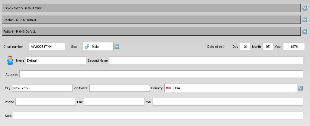
Si prega di notare come nella seconda parte dello schemo sia possibile andare a modificare le informazioni relative alla Clinica, ai Dottori e ai Pazienti.
Premere il pulsante ![]() Avanti posizionato in basso a destra dello schermo per procedere alla definizione del caso.
Avanti posizionato in basso a destra dello schermo per procedere alla definizione del caso.
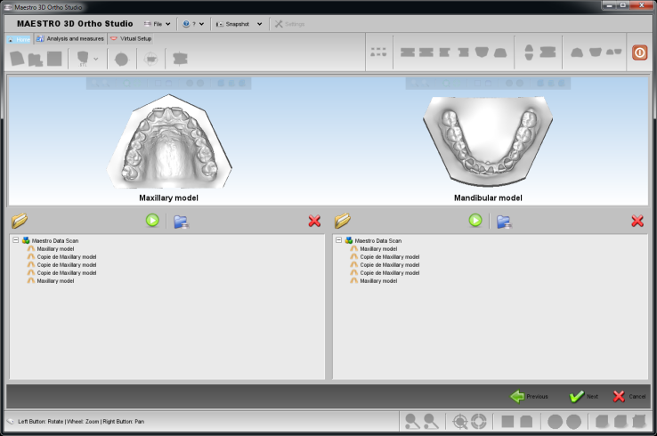
Per andare a selezionare il modello mascellare e mandibolare, si possono scegliere tre strade:
- scegliere il modello dall'albero delle scansioni, (se si dispone di uno scanner dentale della linea Maestro 3D).
-
 importare un modello STL da disco usando il bottone Apri files da disco.
-
 importare un modello da disco utilizzando il pulsante Import Ortho files from disk.
-
 inizia una sessione di scansione cn lo scanner dentake Maestro 3D.
Aprire un caso esistente
Per aprire un caso esistente premere il pulsante ![]() Apri caso situato nella toolbar principale.
Nell'albero dei casi, in basso allo schermo è possibile selezionare un caso esistente relativo a quel paziente selezionato. Per vedere tutti i casi di un dato paziente, premere il pulsante
Apri caso situato nella toolbar principale.
Nell'albero dei casi, in basso allo schermo è possibile selezionare un caso esistente relativo a quel paziente selezionato. Per vedere tutti i casi di un dato paziente, premere il pulsante ![]() Seleziona paziente situato nella sinistra dello schermo.
In questa fase è possibile cambiare le informazioni relative alla clinica, al dottore al paziente. E' possibile muovere un caso da un paziente ad un paziente sconosciuto e viceversa, semplicemente cliccando e trascinando il caso selezionato da una cartella all'altra.
Seleziona paziente situato nella sinistra dello schermo.
In questa fase è possibile cambiare le informazioni relative alla clinica, al dottore al paziente. E' possibile muovere un caso da un paziente ad un paziente sconosciuto e viceversa, semplicemente cliccando e trascinando il caso selezionato da una cartella all'altra.
Premere il pulsante ![]() Avanti situato in basso a destra dello schermo per procedre.
Premere il pulsante
Avanti situato in basso a destra dello schermo per procedre.
Premere il pulsante ![]() Annulla per annullare la procedura in corso.
Annulla per annullare la procedura in corso.
L'immagine sotto mostra il processo di apertura di un caso esistente.
Cambiare il sistema di riferimento
Per cambiare il sistema di riferimento dei due modelli è necessario premere il pulsante ![]() Cambiare il sistema di riferimento - Posizione iniziale.
Cambiare il sistema di riferimento - Posizione iniziale.
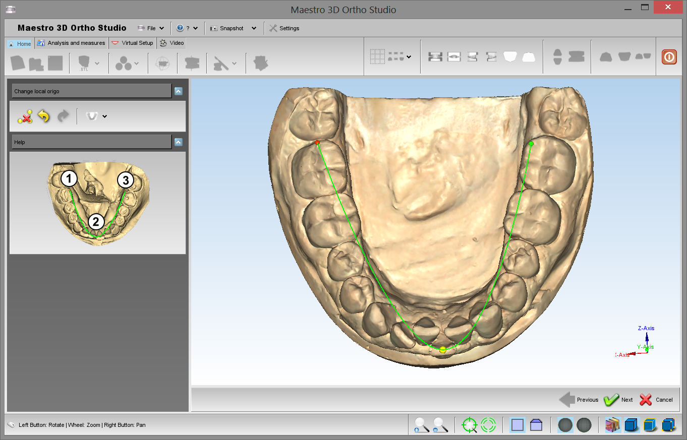
Fare dobbio click sopra il modello per aggiungere un nuovo punto alla spline come mostrato nella figura sottostante. In questo modo si definirà una posizione iniziale del sistema di riferimento dei modelli.
Premere Avanti oppure ![]() Cambiare il sistema di riferimento - Posizionamento preciso per andare al secondo passaggio.
Cambiare il sistema di riferimento - Posizionamento preciso per andare al secondo passaggio.
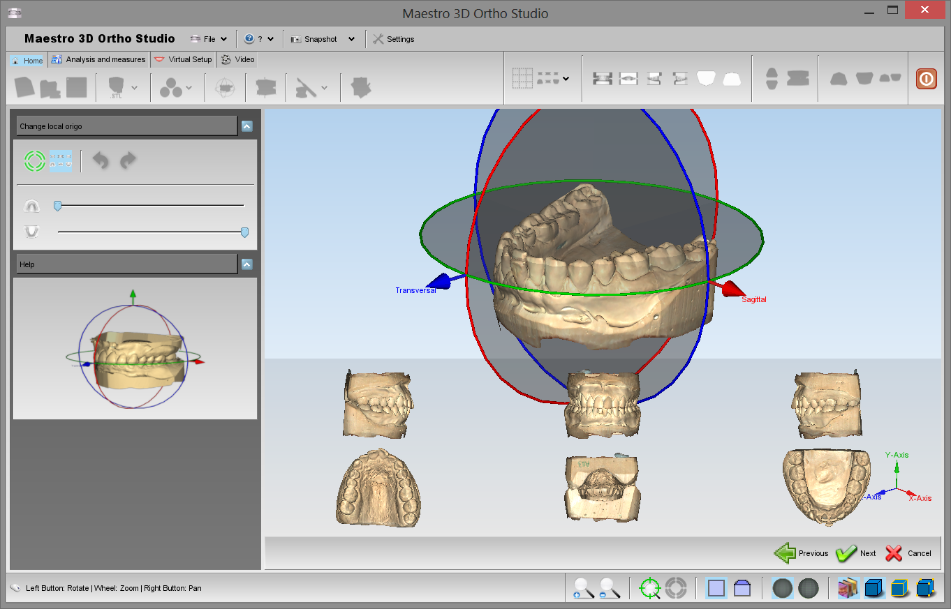
Nell'area di editing apparirà un manipolatore. (Si veda l'immagine sotto). Il centro del manipolatore rappresenta il centro del sistema di coordinate. La freccia rossa rappresenta l'asse X, la verde l'asse Y e la blu l'asse Z.
Premere[[image:next.png] Avanti per applicare i cambiamenti fatti.
Si ricorda che per non perdere i cambiamenti fatti è necessario salvare il lavoro periodicamente. Per salvare premere il pulsante ![]() the Salva caso situato nella toolbar principale.
the Salva caso situato nella toolbar principale.
Creazione Basi Virtuali
Per aggiungere le basi virtuali ai modelli, premere ![]() Aggiungi basi virtuali.
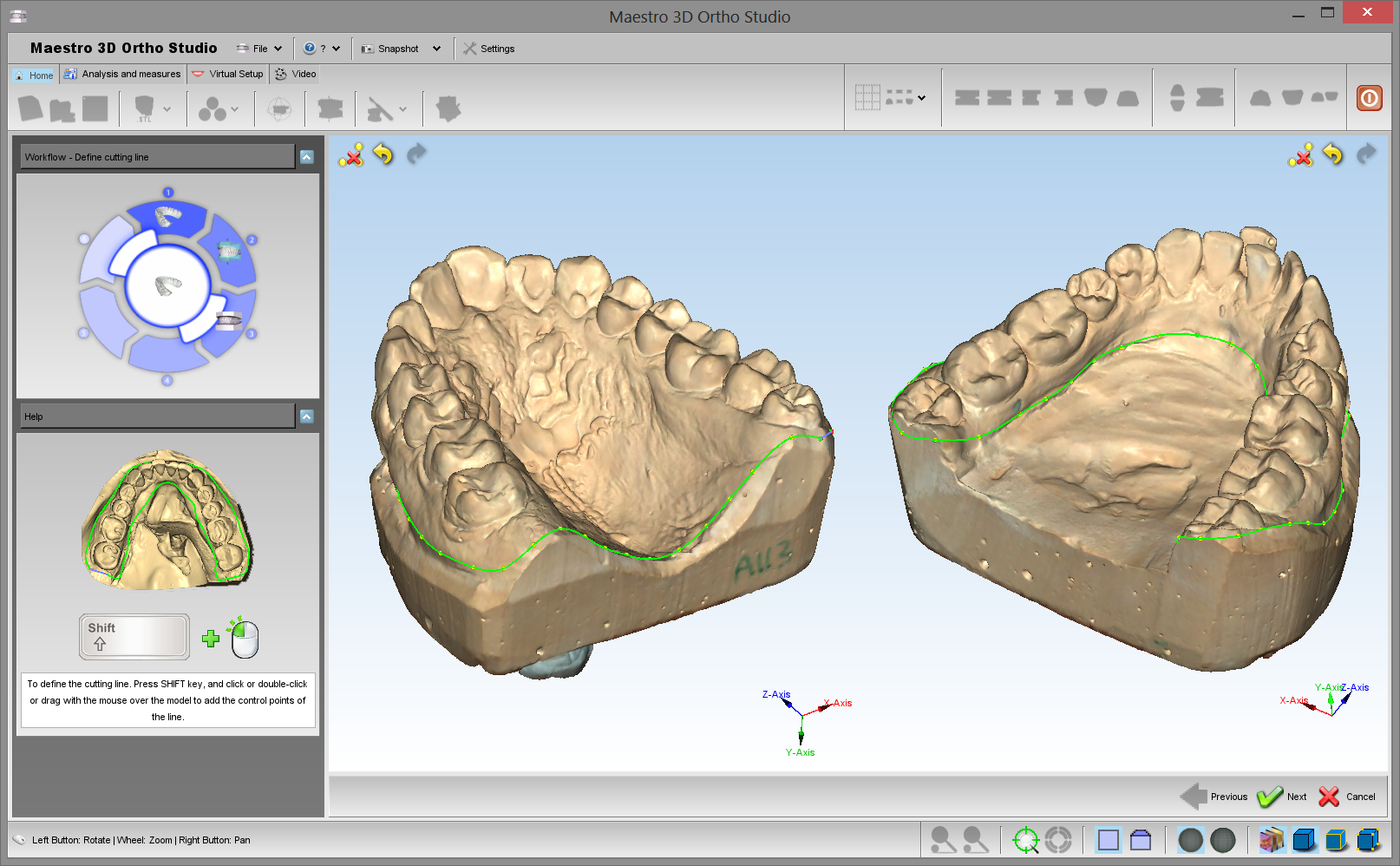
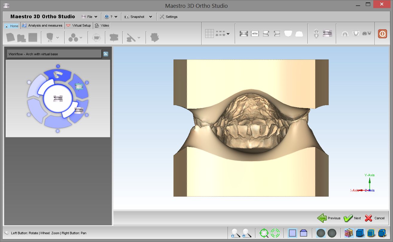
Il primo passo è quello di definire una linea di taglio per rimuovere l'area dei modelli non necessaria. E' possibile definire una linea di taglio su entrambi i modelli. Successivamente il software detecterà automaticamente l'area da rimuovere.
Aggiungi basi virtuali.
Il primo passo è quello di definire una linea di taglio per rimuovere l'area dei modelli non necessaria. E' possibile definire una linea di taglio su entrambi i modelli. Successivamente il software detecterà automaticamente l'area da rimuovere.
|
CONSIGLIO: SHIFT + doppio click con il tasto sinistro del mouse per aggiungere un punto alla linea di taglio. |
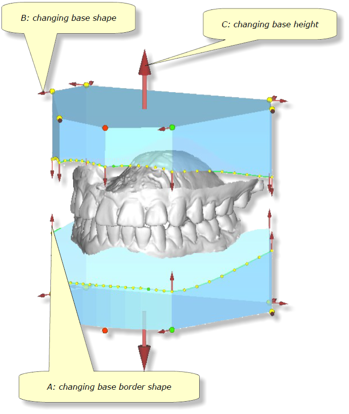
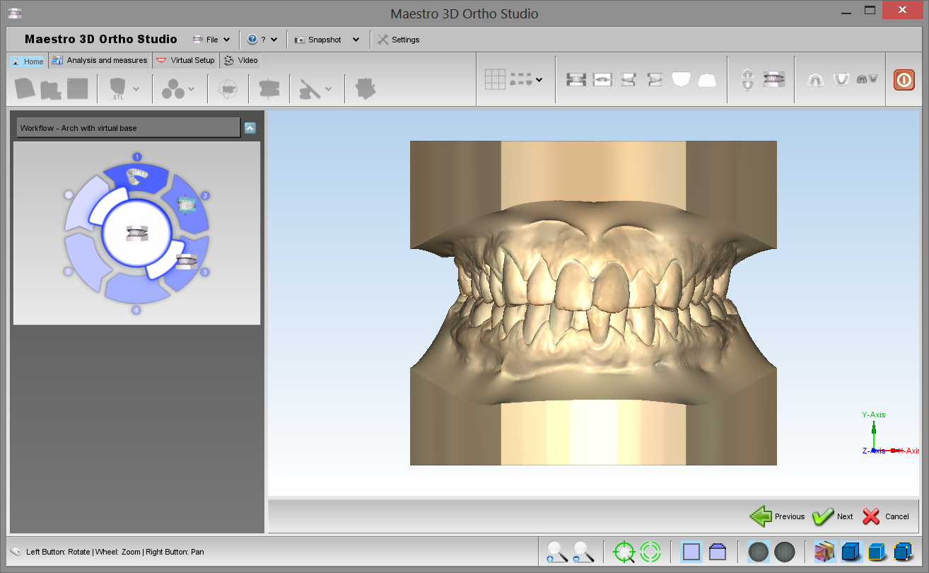
Il secondo step consiste nell'andare ad editare la base virtuale. E' possibile scegliere fra alcuni tipi di basi predefinite, come: ABO, Parallel, Tweed e Ricketts.
E' inoltre possibile eseguire le seguenti operazioni:
A: cambiare il bordo della base:
trascinare un punto situato sul bordo della base premendo SHIFT + tasto sinistro del mouse. E' inoltre possibile disegnare un nuovo bordo della base. Tenendo premuto il tasto SHIFT e il tasto sinistro del mouse si può disegnare un nuovo bordo andando a trascinare la zona vicina alle estremità della base dove sono presenti i punti di controllo della linea di bordo. Inoltre trascinando le frecce locate agli estremi della base è possibile spostare e dimensionare la base stessa.
B: cambiare la forma della base:
trascinando i punti e le frecce situate agli angoli della base virtuale è possibile cambiare la forma della base stessa. Durante tutte le operazioni di editing le relazioni fra angoli e lunghezze del modello di base scelta saranno preservati.
C: cambiare l'altezza della base:
trascinando le frecce poste alle estremità superiore ed inferiore delle due basi è possibile cambiarne l'altezza. Questa opzione è disabilitata per le basi di tipo ABO.
Tutte le operazioni di editing riguardanti la creazione delle basi virtuali, avvengono tramite la pressione del tasto SHIFT + il pulsante sinistro del mouse. Usando invece
Usando il checkbox “Cambiamenti Simmetrici” tutte le operazioni fatte risulteranno simmetriche per le due basi.
Alla fine del processo, premere Next per finalizzare la procedura.
Analisi e Misure
Ispezione Occlusale
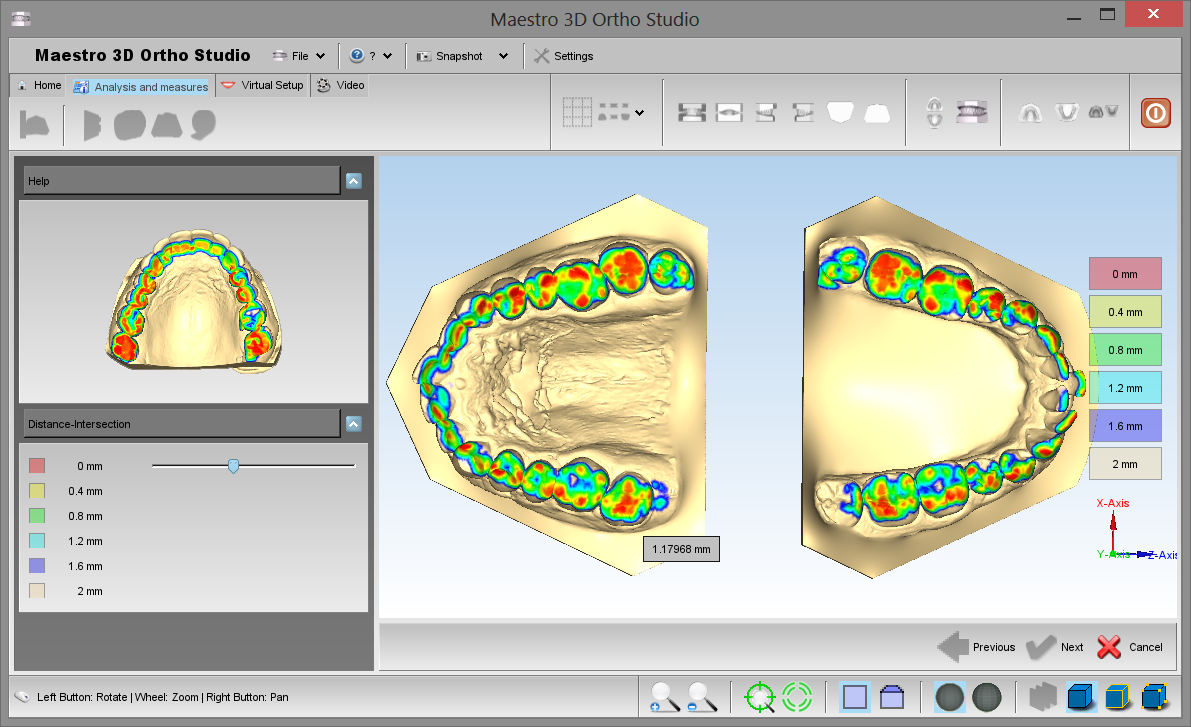
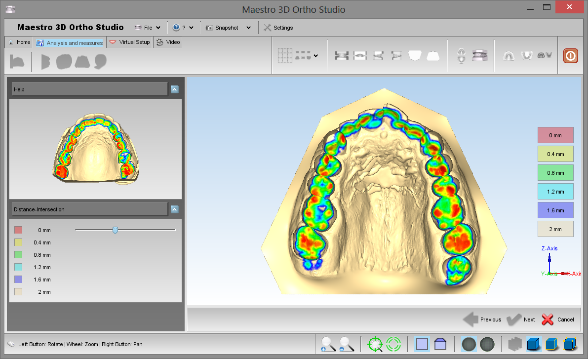
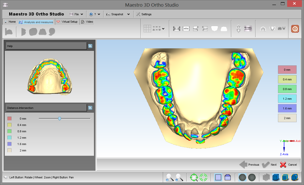
Per visualizzare e analizzare l'occlusione fra i modelli mascellare e mandibolare premere il pulsante ![]() Ispezione Occlusale. Dopo questo compariranno sullo schermo le due arcate colorate secondo una mappa di colori che indica la distanza fra le due arcate.
Ispezione Occlusale. Dopo questo compariranno sullo schermo le due arcate colorate secondo una mappa di colori che indica la distanza fra le due arcate.
E' inoltre possibile fare SHIFT + doppio click con il mouse sopra il modello per visualizzare il valore esatto della distanza nel punto cliccato.
La seguente immagine mostra un esempio di visualizzazione dell'occlusione fra le due arcate. Per visualizzare entrambe le arcate premere ![]() Mostra tutto.
Mostra tutto.
La seguente immagine mostra l'occlusione dell'arcata mascellare. Per visualizzare l'arcata mascellare premere ![]() Mostra Mascella.
Mostra Mascella.
Per visualizzare la mandibola premere ![]() Mostra Mandibola.
Mostra Mandibola.
Sezioni
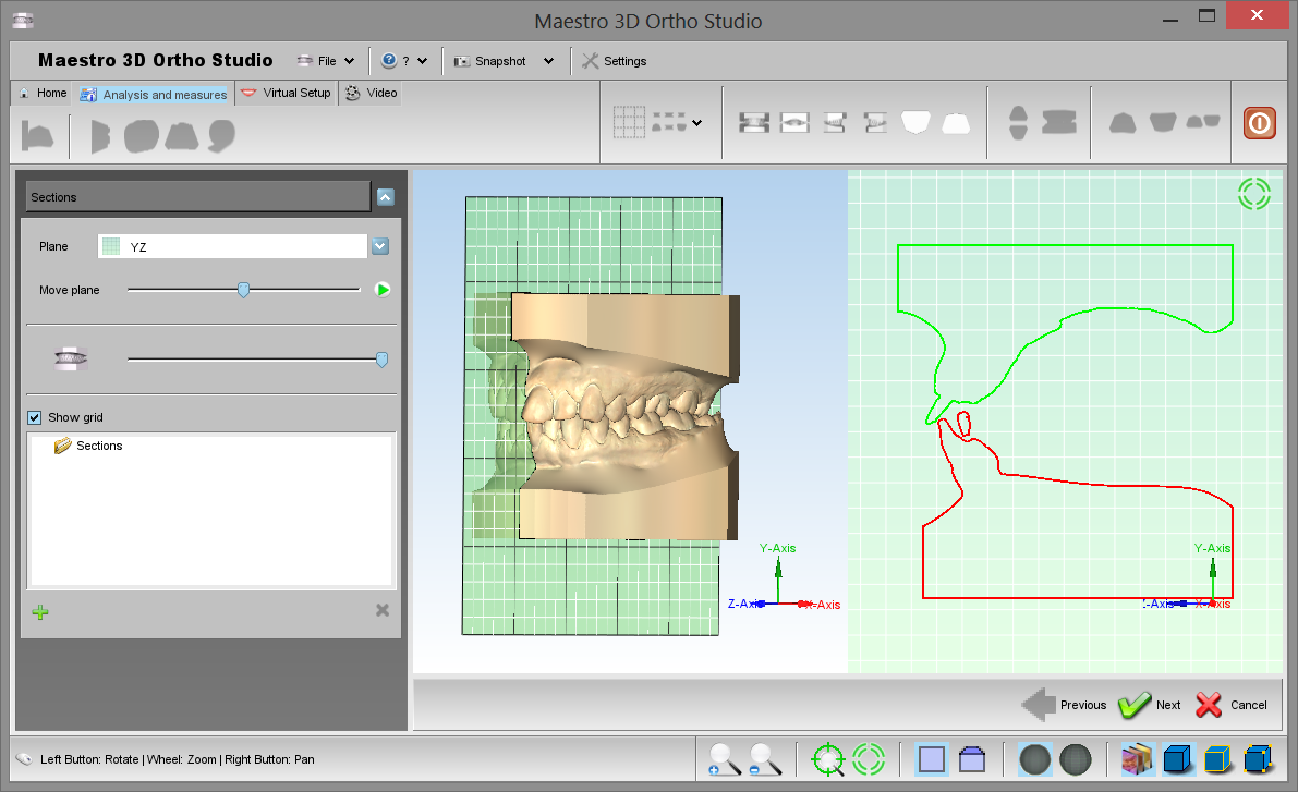
Per effettuare l'analisi delle sezioni premere il pulsante ![]() Sezioni. E' possibile muove il piano della sezione sopra i modelli e andare ad effetture le misure 2D.
Mediante il toolbox sulla sinistra dello schermo è possibile cambiare il piano, cambiare la trasparenza dei modelli e visualizzare l'animazione delle sezioni.
Si veda l'immagine sotto:
Sezioni. E' possibile muove il piano della sezione sopra i modelli e andare ad effetture le misure 2D.
Mediante il toolbox sulla sinistra dello schermo è possibile cambiare il piano, cambiare la trasparenza dei modelli e visualizzare l'animazione delle sezioni.
Si veda l'immagine sotto:
|
CONSIGLIO: SHIFT + doppio click con il pulsante sinistro del mouse per aggiungere un punto sulla griglia 2D. |
Teeth Measures
In order to perform the analisys of the distances between theeth, select the arch to inspect using the ![]() Show Maxillary button button or the
Show Maxillary button button or the ![]() Show Mandibular button and then press the
Show Mandibular button and then press the ![]() measures button.
measures button.
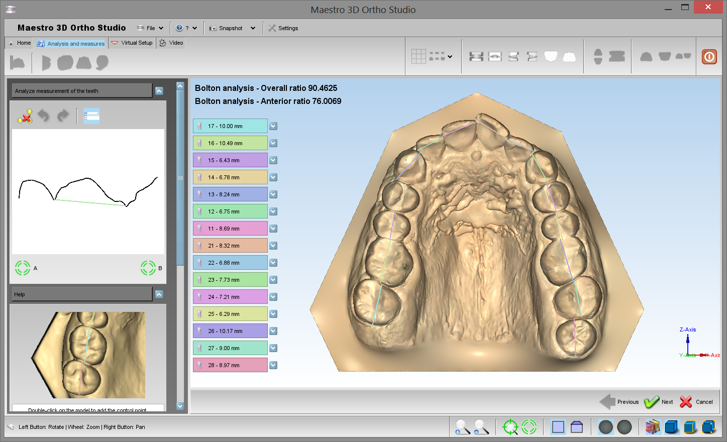
The image shows the process of measuring distances between theeth in the maxillary model. As for the process of the cutting line definition, it is possible to add, remove or modify the position of the points.
For each line segment defined by two consecutive points the current length of the segment is showed.
On the left side of the screen the total length and the average length of the segments are showed too.
Using the ![]() Undo button and the
Undo button and the ![]() Redo button it is possible Undo / Redo all the operations performed.
It is also possible to clear the measure using the [[image::Polyline.delete.png]] Reset button.
In order to save the measures, after pressing the [[image::next.png] Next button, please remember to press the
Redo button it is possible Undo / Redo all the operations performed.
It is also possible to clear the measure using the [[image::Polyline.delete.png]] Reset button.
In order to save the measures, after pressing the [[image::next.png] Next button, please remember to press the ![]() Save case button located in the main toolbar.
Save case button located in the main toolbar.
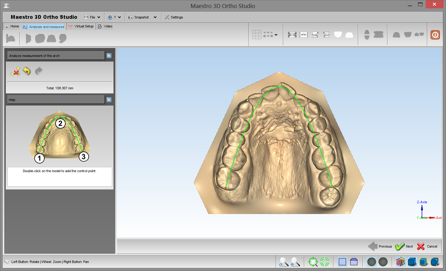
Arch Length
In order to perform the analisys of the arch length, select the arch to inspect using the ![]() Show Maxillary button button or the
Show Maxillary button button or the ![]() Show Mandibular button and then press the
Show Mandibular button and then press the
![]() measures button.
measures button.
|
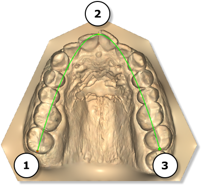
TIPS: double-click with left mouse button to add a point of the spline to compute the arch length. |
Put the points in the following order to define a correct spline. It's possible to add more than 3 points.
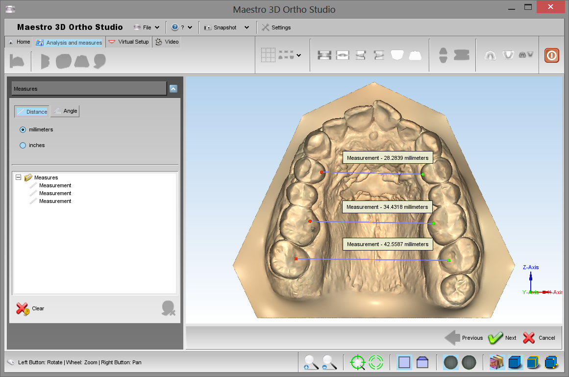
Free Measures
In order to perform the measures of length or angles, select the arch to inspect using the ![]() Show Maxillary button button or the
Show Maxillary button button or the ![]() Show Mandibular button and then press the
Show Mandibular button and then press the ![]() measures button.
measures button.
|
TIPS: double-click with left mouse button to add a point. |
Virtual Setup
With this feature, you can make a setup of both jaws and create all the models needed to complete the treatment. It's possible to add the custom attachments and the label 3D.
Tooth Segmentation
Detect Margin
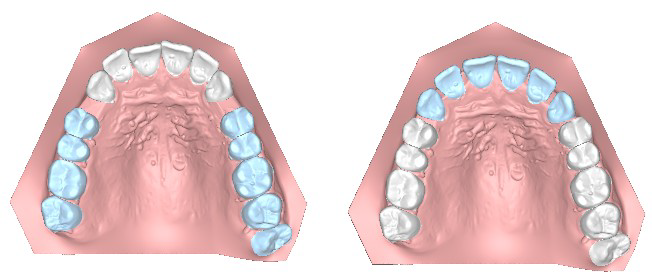
In order to perform the tooth segmentation, select the arch to segment using the ![]() Show Maxillary button or the
Show Maxillary button or the ![]() Show Mandibular button and then press the
Show Mandibular button and then press the ![]() Tooth Segmentation button. Before this it's necessary complete the measurement of individual teeth.
Tooth Segmentation button. Before this it's necessary complete the measurement of individual teeth.
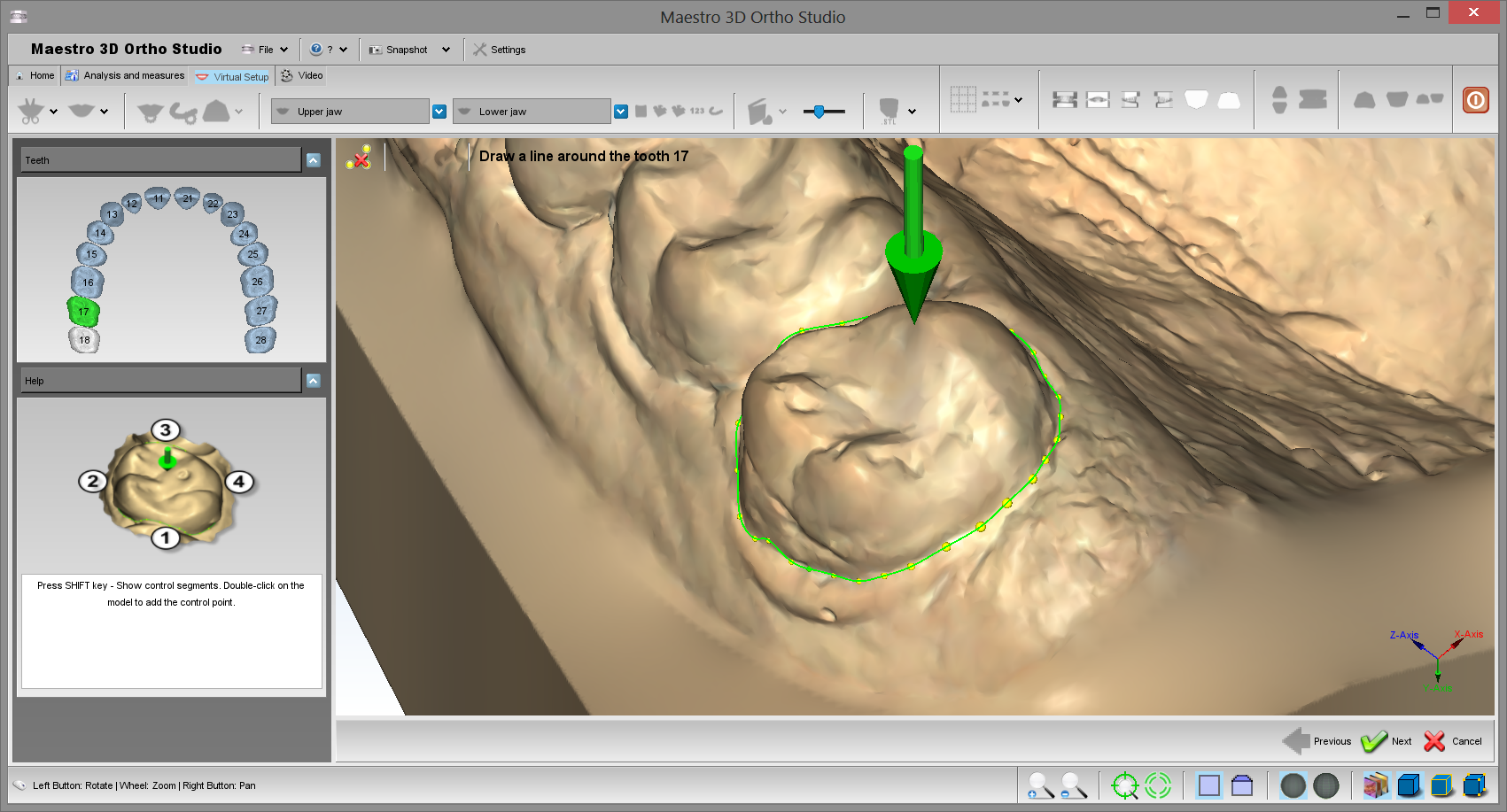
The first step is identify the margin of the tooth. See the image below.
To identify the margin of the tooth, double-click with the mouse near the margin to add a new control point as showed below:
Every two points entered by the user, the software makes a line near on the margin of the tooth. Usually is enough 4 clicks to draw a margin, as shown in figure. If the autocomplition of the line is not correct, press CTRL + Z or press ![]() button and try to add a new click in a different position example closer to the previous point.
button and try to add a new click in a different position example closer to the previous point.
|
TIPS:
|
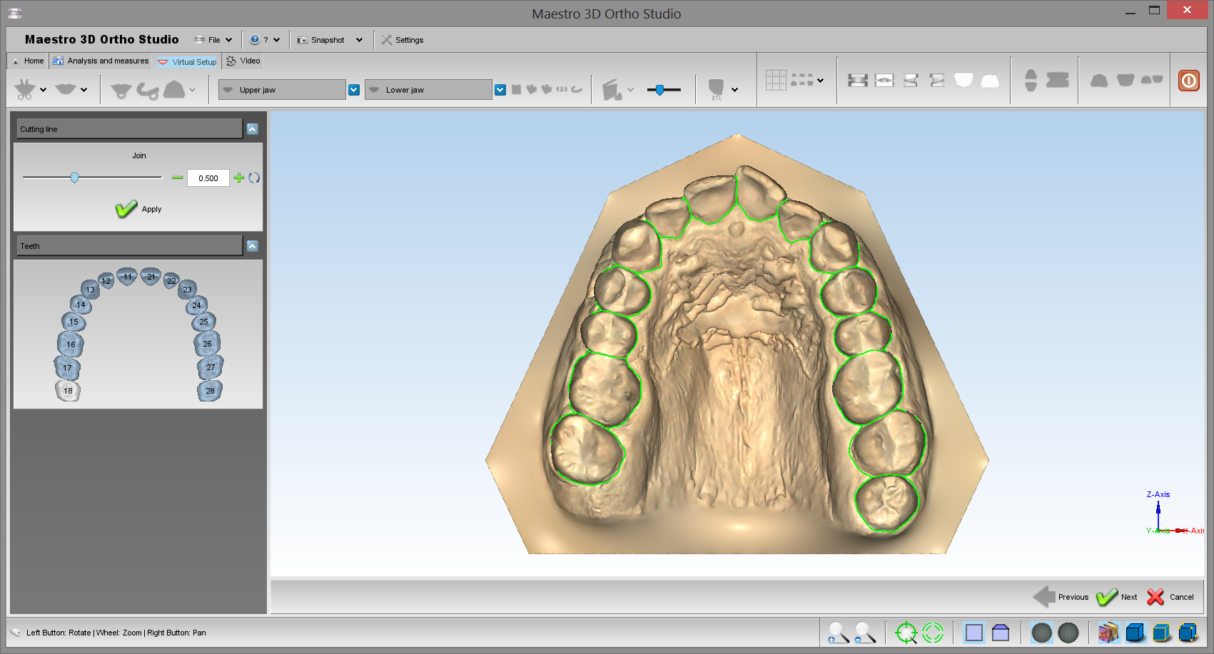
Cutting Line
In order to perform the cutting line of the tooth segmentation, select the arch to segment using the ![]() Show Maxillary button or the
Show Maxillary button or the ![]() Show Mandibular button and then press the
Show Mandibular button and then press the ![]() Cutting line button. Before this it's necessary complete the previous step of Detec Margin.
See the image below:
Cutting line button. Before this it's necessary complete the previous step of Detec Margin.
See the image below:
|
TIPS:
|
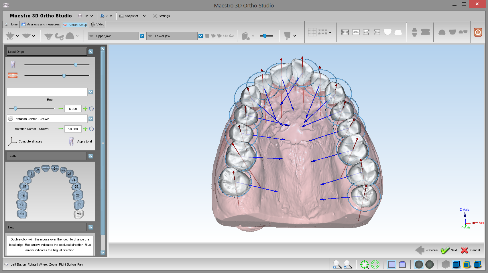
Tooth Local Origo
In order to perform the local origo of each tooth, select the arch to segment using the ![]() Show Maxillary button or the
Show Maxillary button or the ![]() Show Mandibular button and then press the
Show Mandibular button and then press the ![]() Change local origo button. Before this it's necessary complete the previous step of Cutting Line.
See the image below:
Change local origo button. Before this it's necessary complete the previous step of Cutting Line.
See the image below:
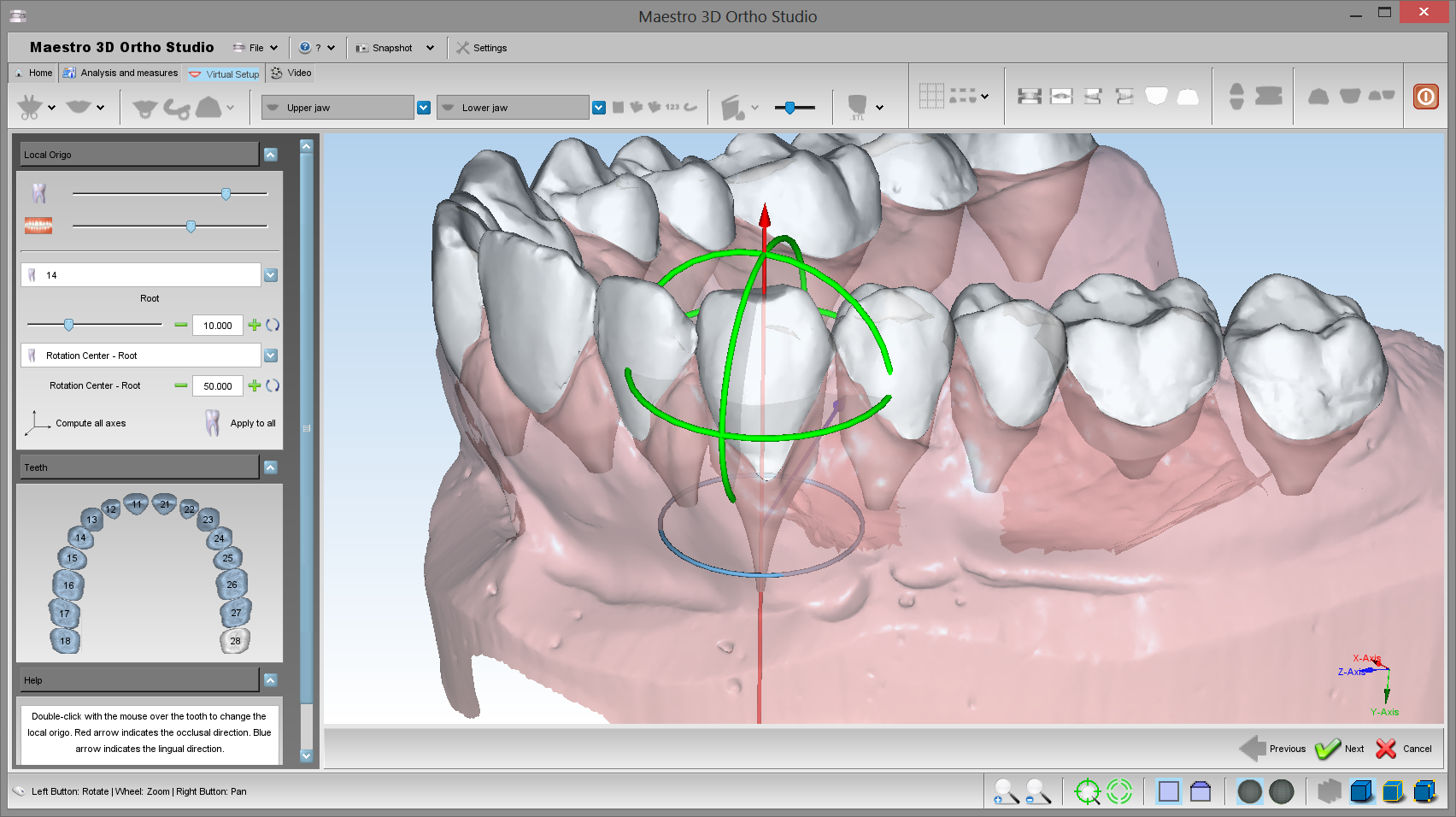
To change the local origo of a tooth, double click over the tooth and use the manipulator to change the origo. When you change the local origo the virtual root of the tooth change direction. Use the left toolbox to change the root dimension when a tooth is selected.
See the image below:
|
TIPS: click with center mouse button to change the rotation center of the trackball. |
Virtual Setup
In order to perform the virtual setup, press ![]() the Virtual Setup button.
the Virtual Setup button.
In this step you can translate and rotate the teeth in order to obtain the desired final position. To select a tooth, click with left mouse button over a tooth.
|
TIPS: SHIFT + left mouse button to translate the teeth selected. CTRL + left mouse button to rotate. Click with the middle mouse button to change the center of rotation of the trackball. |
Take a look to the GUI on the left of the screen that allows to access to all the functionalities of the Virtual Setup.
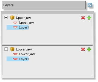
Layers
The layers are the steps that are useful to work with some groups of teeth in different period, i.e.:
you can move the posterior teeth and build a layer1.
than you can move the anterior teeth and build a layer2.
In this way when the software builds a set of virtual models, it is obtained:
| Original model | |
| virtual model (1) | Clear aligner 1 |
| virtual model (2) | Clear aligner 2 |
| ... | ... |
| Layer1 | Clear aligner L1 |
| virtual model (k) | Clear aligner k |
| virtual model (k+1) | Clear aligner k+1 |
| Layer2 | Clear aligner L2 |
So the first set of aligners don't move all teeth but only the posterior teeth. Only after some weeks, when you start to the layer1 you are ready to move the the anterior teeth.
It's possible to work only with the last layer. If you select a different layer, all
functionalities will be disabled.
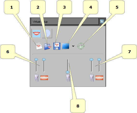
Main toolbox
- 1) start a new setup project.
- 2) open an existing setup project.
- 3) exports the current setup project.
- 4) split the screen.
- 5) show/hide tooth manipulator.
- 6) show animation.
- 7) change teeth/gum transparency.
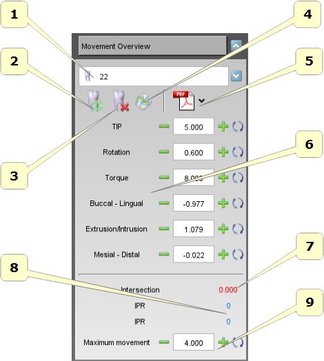
Movement Overview
With this toolbox it's possible to select a tooth from the combo menu and access to all operations of the single tooth.
- 1) list of all teeth.
- 2) reset the position of the selected tooth.
- 3) extract and restore the selected tooth.
- 4) movements in the canonical directions of the selected tooth. The rotations are expressed in degrees and translations in millimeters.
- 5) this value is the maximum movement of the selected tooth. The tooth that exceeds this value is colored red. It's just a visible warning.
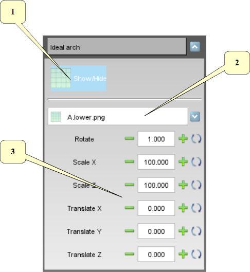
Ideal Arch
With this toolbox it's possible to show an ideal arch in the editing area. This can be used as a visual guide to move the teeth.
- 1) show/hide the ideal arch.
- 2) list of available ideal arch. To add a new arch:
- add new images as png file 32 bit with alpha channel (if you want to use the trasparency) into the subfolder idealarch under the ortho studio installation folder.
- 3) rotate, scale and translate the ideal arch to find the correct position.
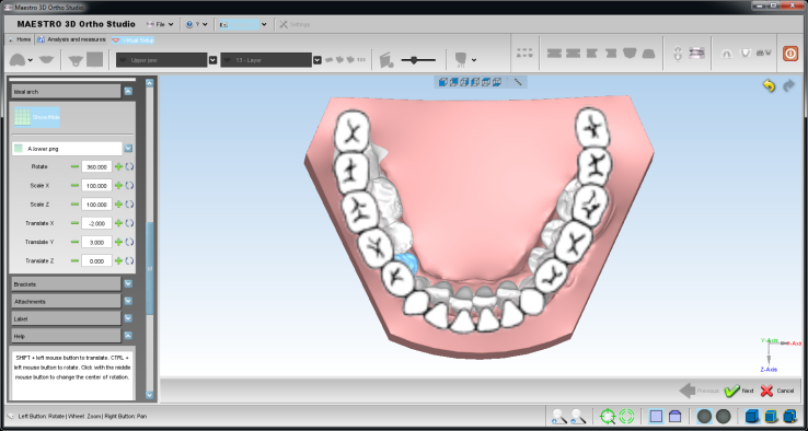
Below an example of an ideal arch.
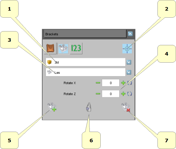
Brackets Module
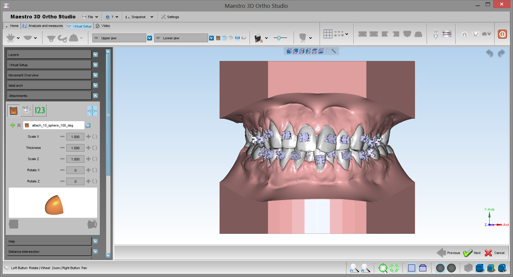
With this toolbox it's possible too add the brackets over the teeth.
- 1) list of available brackets brand.
- 2) list of available brackets type for the selected brand.
- 3) add a new bracket. Hold SHIFT and double-click with the mouse over the tooth to add it.
- 4) remove the selected bracket.
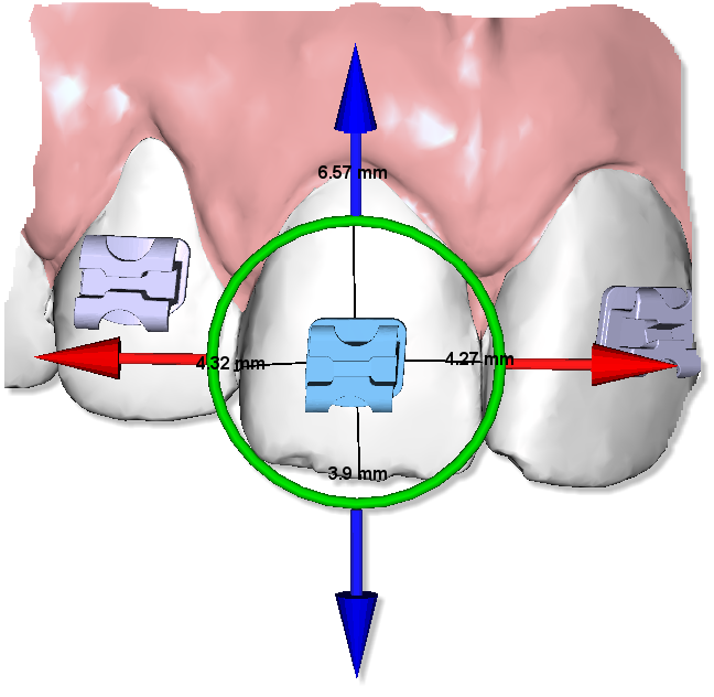
Below, there is an example of a bracket with manipulator.
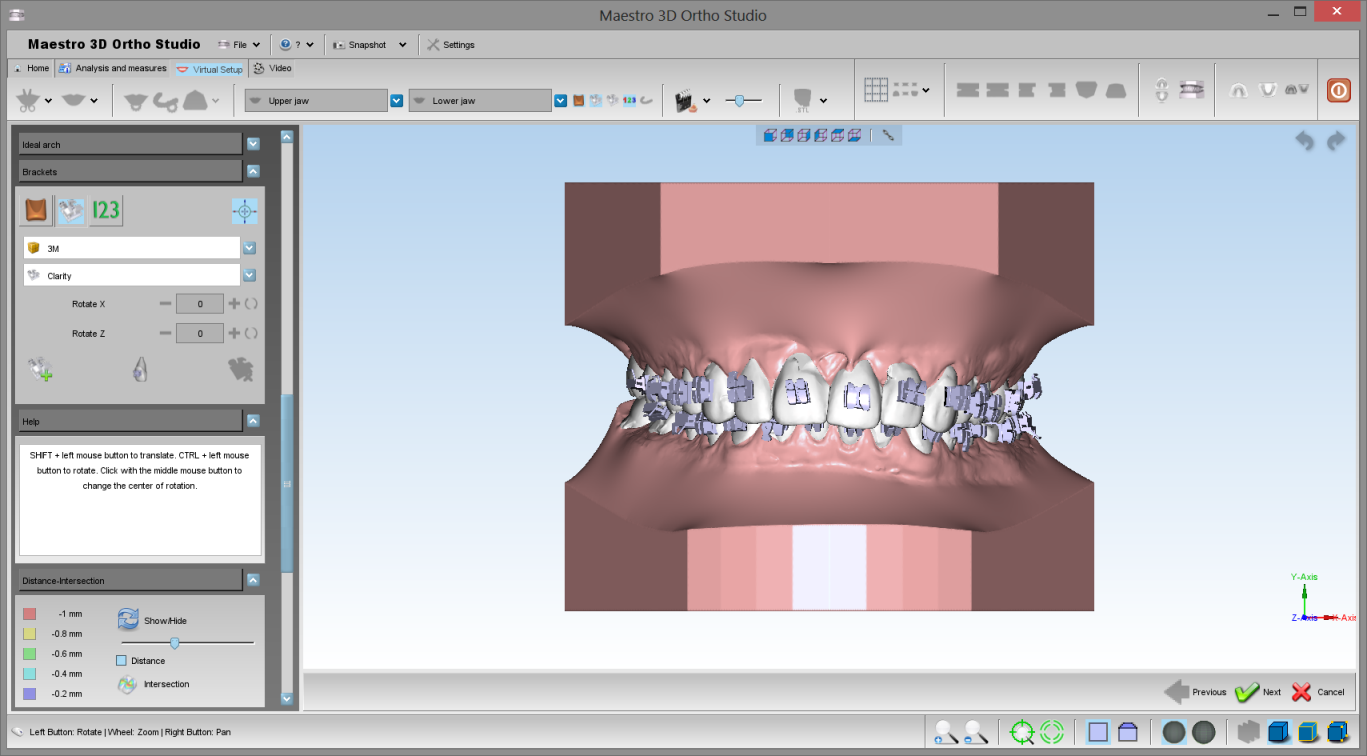
Another example of a case with all brackets.
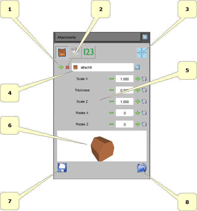
Attachments
- 1) add a new attach. Hold SHIFT and double-click with the mouse over the tooth to add it.
- 2) remove the selected attach.
- 3) list of available attachments.
- 4) thickness of the attachment.
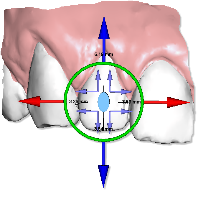
Below, there is an example of an attachment with manipulator.
Label
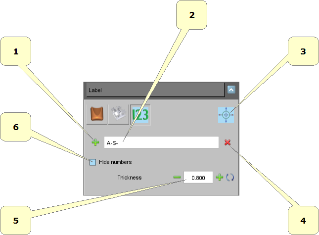
It's possible to put a 3D text over the gum or over the teeth. It's useful to identify the models after printed.
- 1) add a new label. Hold SHIFT and double-click with the mouse over the gum or over the teeth.
- 2) prefix of the label, i.e.: initials of the patient's name.
- 3) remove the selected label.
- 4) thickness of the label.
Below an example of two label over the model.
The written 123 will be replaced with the correct numeration after the build of the virtual models.
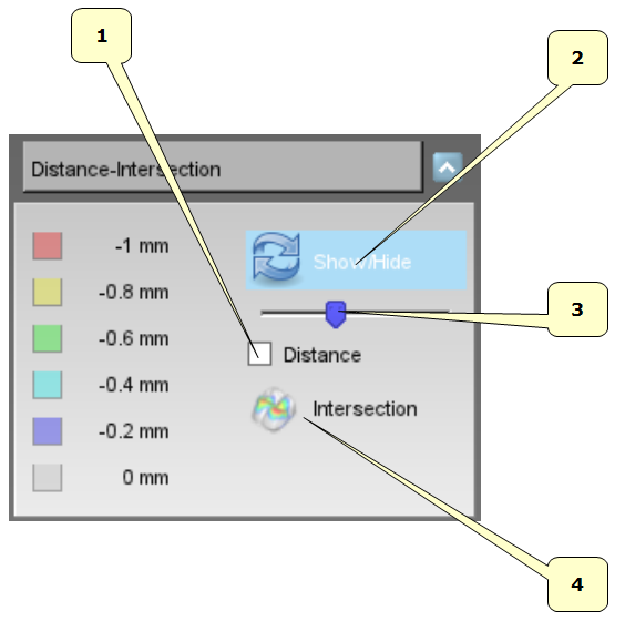
Show intersection/distance
- 1) teeth intersaction or teeth distnce.
- 2) scale of the measures.
- 3) show/hide color map over the teeth.
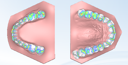
Below an exampe of teeth distance.
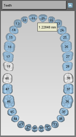
Teeth informations
Move the mouse over a tooth, it shows an informative label about the tooth's movement, see the image below.
Models Builder
In order to perform the models builder, select the arch using the ![]() Show Maxillary button or the
Show Maxillary button or the ![]() Show Mandibular button and then press the
Show Mandibular button and then press the ![]() Models builder button.
Models builder button.
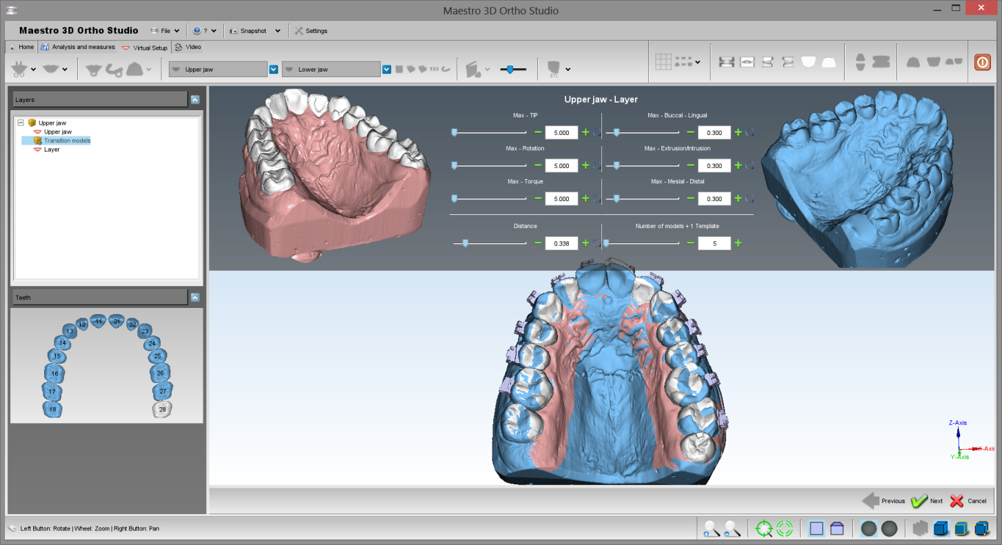
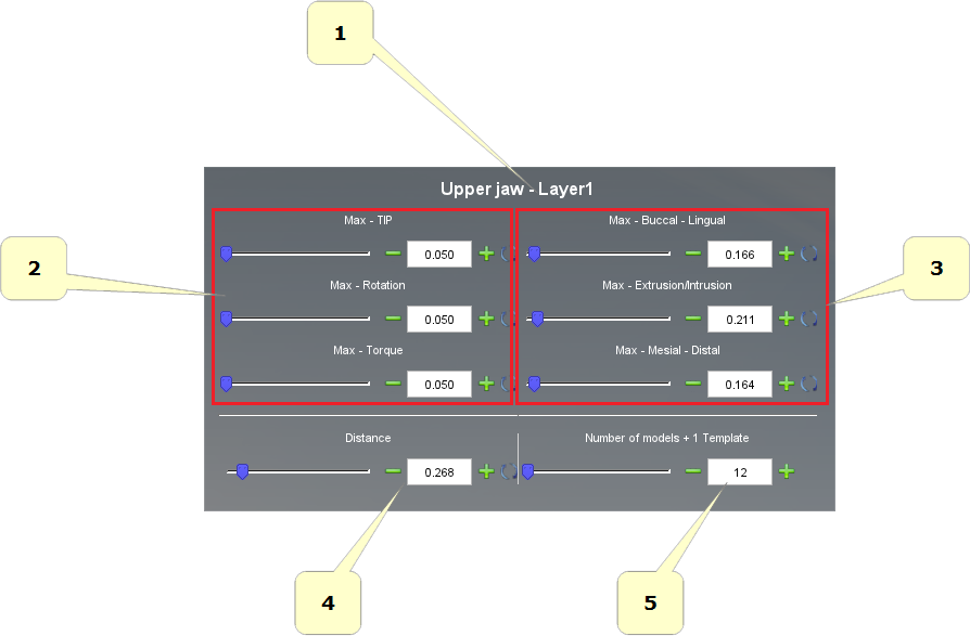
In the left of the screen there is a treeview with all layers. Between two layers there is a transition models item. Select it to choose the movement of the teeth for each virtual model. Belown an example of the models builder function:
in detail:
- 1) start and end position, from layer(n) to layer(n+1). In this example: from Upper Jaw to Layer.
- 2) information about distance:
- Average: is the average value of the movement of all tetth.
- Max: is the value of the max movement between all teeth.
- 3) desidered value of the max movement of the teeth for each virtual model.
- 4) number of virtual models that will be generated.
- 5) real value of the max movement of the teeth for each virtual model.
- 6) this label indicates that there will be generated a template model to stick attachments/brackets.
Cut and Close
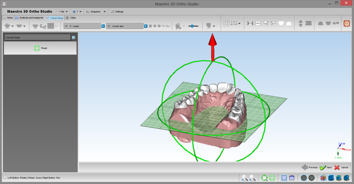
This feature was created to remove from virtual models all surface that it's not necessary for the construction of invisible aligners. This saves a lot of print material.
In order to perform the cut and close, select the arch using the ![]() Show Maxillary button or the
Show Maxillary button or the ![]() Show Mandibular button and then press the
Show Mandibular button and then press the ![]() Cut and Close button.
Cut and Close button.
Rotate the plane with the green circles and translate the plane with the red arrows. Press the ![]() Next button to cut and close all virtual models.
Next button to cut and close all virtual models.
