Maestro 3D Ortho Studio - User Manual
(→= Procedures for downloading an orthoipad file for viewing) |
(→Procedures for downloading an orthoipad file for viewing) |
||
| Line 1,137: | Line 1,137: | ||
=== Procedures for downloading an orthoipad file for viewing === | === Procedures for downloading an orthoipad file for viewing === | ||
<div align="justify"> | <div align="justify"> | ||
| + | Tap the ‘Files’ button on the main menu at the bottom of the screen. Then tap the button at the bottom of the form labeled “FTP Import”. The following form will display. The three input fields (Address, Username and Password) will be empty on first use. | ||
</div> | </div> | ||
Revision as of 17:22, 14 November 2013
Introduction to the use of Maestro 3D Ortho Studio software
The aim of this document is to introduce the user to the use of the Ortho Studio software, in a simple and quick way. Please read this manual carefully before making use of the Ortho Studio software.
Introduction
Maestro 3D Ortho Studio is a very powerful and easy software for orthodontics. The principal features available are:
- Patient, Surgery And Doctor info handling using AGE DB.
- Choice of local origo of mandibular and maxillary arcs.
- Virtual base creation / modification and stitching to mandibular and maxillary arcs.
- Virtual Setup.
- Occlusion inspection between mandibular and maxillary models.
- Analysis of distance, measures and sections.
Software Installation
To install the Maestro 3D Ortho Studio software, double click with left mouse button on the file: Maestro.3D.Ortho.Studio.vx.xx.xxx.Setup.exe which is in the CD\DVD.
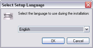
Step 1: Select the installation language.
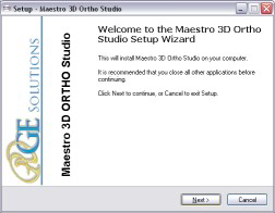
Step 2: A welcome installation window of Maestro 3D Ortho Studio appears. Press Next to continue.
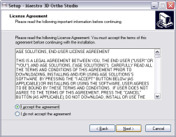
Step 3: Please read the license agreement carefully, accept it as shown in the red circle and press Next to continue.
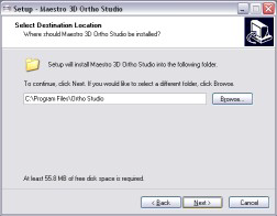
Step 4: Select the destination folder. (We recommend to use the default folder). Press Next to continue.
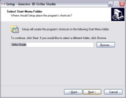
Step 5: Select the menu start folder. (We recommend to use the default folder). Press Next to continue.
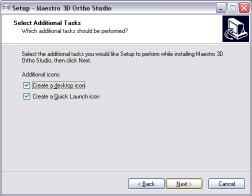
Step 6: Select, if you want, a program icon on the desktop and into the quick launch bar. Press Next to continue.
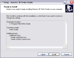
Step 7: At this point a summary of installation information appears. Press Install to install the software.
A progress bar shows the progress of the installation process. Step 8: Installation complete. Press Finish to complete the installation.
| Use Windows 7 or 8 - 64 bit.
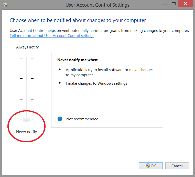
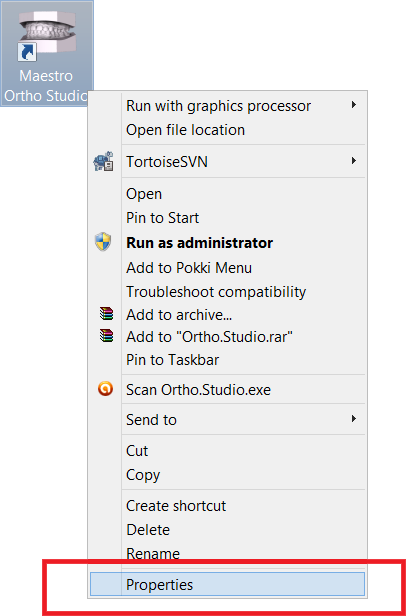
Install all Windows update available. Install the last graphics card available from NVIDIA web site http://www.nvidia.com. Set the slider of UAC (user account control) to put it to a minimum. Right mouse click over software icon and Properties -> Advanced -> (check) Run As Administrator. |
UAC - User Account Control
To avoid difficulties and limitations in the use of the software, it is necessary to set the UAC slider - User Account Control to the minimum value as shown in the picture below.
To log in to the setting window: Control panel-> User Account-> Change Settings User Account Control.
Administrator's Rights
To put in operation the sofware it is necessary to set correctly administrator's rights.
Follow the instructions as shown in the pictures below.
Right button of the mouse on the software's icon to start the contextual menu and select the entry proprieties.
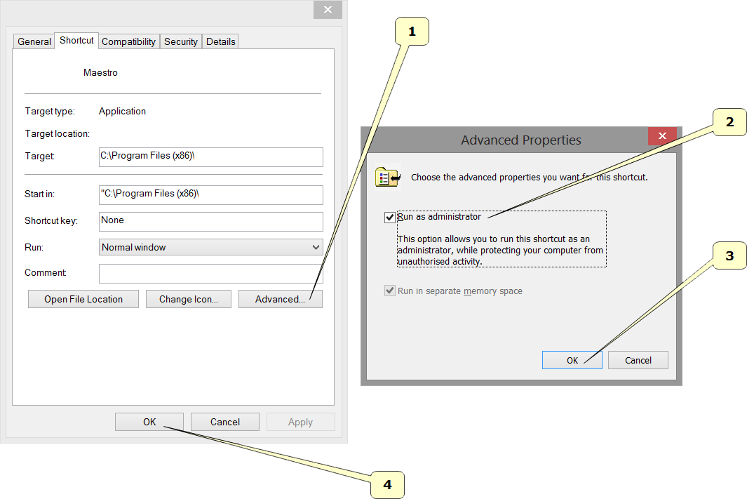
Follow the steps as shown in the sequency from 1 to 4.
- Press the button Advanced.
- Select the voice Run as administrator.
- Press the button Ok.
- Press the button Ok.
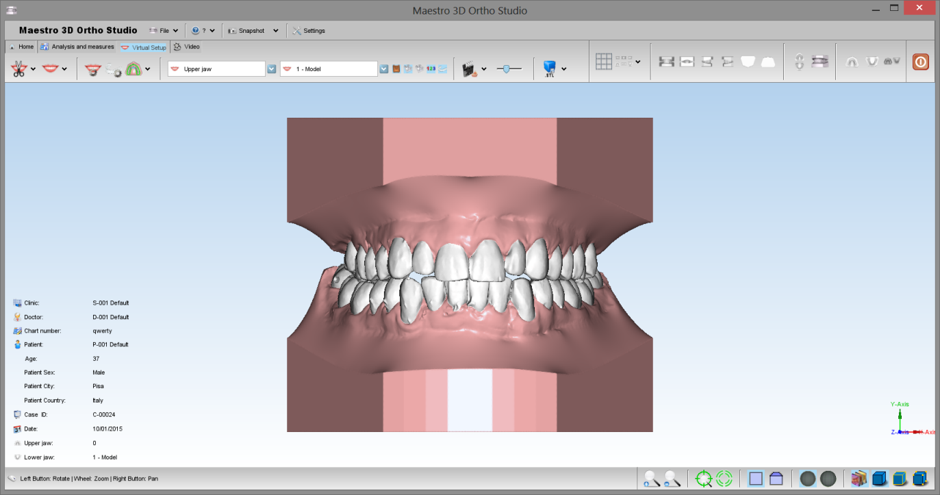
User Interface
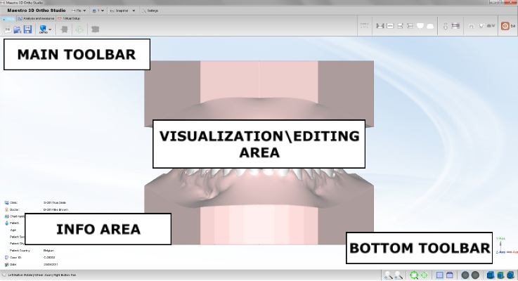
The figure below shows the composition of the user interface.
Main Toolbar
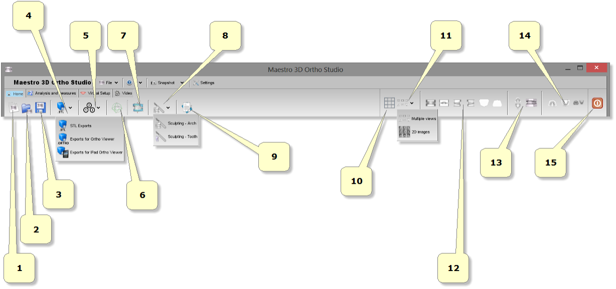
The main toolbar allows the access to the all functionalities of the Ortho Studio Software.
- 1) new case.
- 2) open case.
- 3) save case.
- 4) exports:
- as Ortho: exports the current case in *.ortho file format. Useful to do the digital service for the customers. With Ortho Studio Viewer the customers can see, inspect and measure the models and the virtual setup also.
- as Orthoipad: exports the current case in *.orthoipad file format. Useful to do the digital service for the customers that have the Apple iPad device. With Ortho Studio Viewer iPad the customers can see and inspect the models. Download here: Ortho Studio Viewer iPad
- as Stl: exports the current case in a folder. The folder will contain a *.txt file with the case information and the maxillary and mandibular models in *.Stl file format.
- 5) change local origo.
- 6) change articulation.
- 7) add virtual base.
- 8) sculpting.
- 9) multiple views.
- 10) views:
- front view.
- rear view.
- right side view.
- left side view.
- top view.
- bottom view.
- 11) open/close mouth.
- 12) show maxillary/mandibular/all. Change the view from maxillary to mandibular or all. When you change this from all to maxillary or vice versa, some functionalities of the software can become enabled or disabled.
- 13) exit.
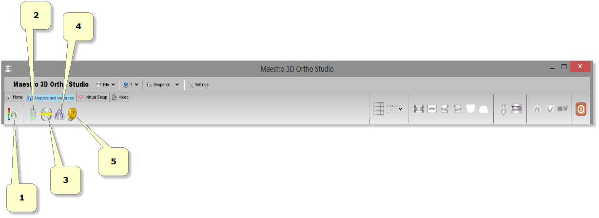
- 1) occlusion inspection: starts the distance computation process between maxillary and mandibular archs.
- 2) cross sections.
- 3) measures of the teeth.
- 4) measures of the arch.
- 5) free measures:
- point-point measures.
- angle measures.
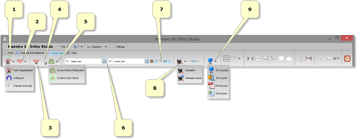
- 1) segmentation:
- teeth segmentation: draw a margin line for each tooth.
- cutting line: separates the tooth from the gum.
- change local origo: adjust local origo and root for each tooth.
- 2) virtual setup.
- 3) models builder.
- 4) cut and close.
- 5) menu list of all virtual models.
- 6) show/hide attachments, brackets, brackets key, labels.
- 7) animation.
- 8) exports:
- as Stl file format.
- as Zip file format.
Bottom Toolbar
The bottom toolbar is the area of the screen containing a progress bar that is displayed and updated during each computation of the program and the controls for changing the visual settings of the visualization/editing area.
- 1) magnify in [Key PGDown]/magnify out [Key PGUp].
- 2) show/hide trackball.
- 3) reset trackball [Key R].
- 4) parallel projection [Key O], perspective projection [Key P].
- 5) smooth shading [Key S], flat shading [Key F].
- 6) show/hide triangles, edges [Key E], vertices [Key V].
Visualization / Editing Area and Info Area
The visualization / editing area is the area of the window in which the models are visualized and all the editing operations are performed.
In the visualization area it is possible to create virtual bases, show the occlusion inspection between maxillary and mandibular arcs, measure distance between teeth and to perform virtual setup.
In order to examine the models displayed in the visualization / editing area camera parameters (position, scale and rotation) can be setted using an instrument called trackball.
The trackball is very simple to use. Just use the Left mouse button dragging to rotate around the model, the mouse wheel to Zoom in / Zoom out and the Right mouse dragging to move (pan) the camera.
The info area of the screen shows the info related to the current Case. In particular the info about Surgery, Doctor and Patient are displayed, also with the Case ID.
Create a New Case and Open an Existing Case
Create a New Case
To create a new case press the ![]() New Case button located in the main toolbar.
The process of creating a new case consists in the following steps:
New Case button located in the main toolbar.
The process of creating a new case consists in the following steps:
- specify the Surgery data (optional)
- specify the Doctor data (optional)
- specify the Patient data (optional)
- specify the relationship between Surgery, Doctor and Patient (optional)
- choose maxillary and mandibular models (required)
To create a new Surgery press the ![]() Add new surgery button, located in the left side of
the screen. After filling the fields of the form that appears in the main side of the screen specifying the
data of the Surgery, press the
Add new surgery button, located in the left side of
the screen. After filling the fields of the form that appears in the main side of the screen specifying the
data of the Surgery, press the ![]() Insert button to add the new Surgery to the database
or the
Insert button to add the new Surgery to the database
or the ![]() Clear button to clear the fields of the form.
Clear button to clear the fields of the form.
In the same way it is possible to create a new doctor pressing the ![]() Add new doctor button and to create a new patient pressing the
Add new doctor button and to create a new patient pressing the ![]() Add new patient button. In order to define a Case it is necessary to press the
Add new patient button. In order to define a Case it is necessary to press the ![]() Select patient button located in the left side of the screen.
Select patient button located in the left side of the screen.
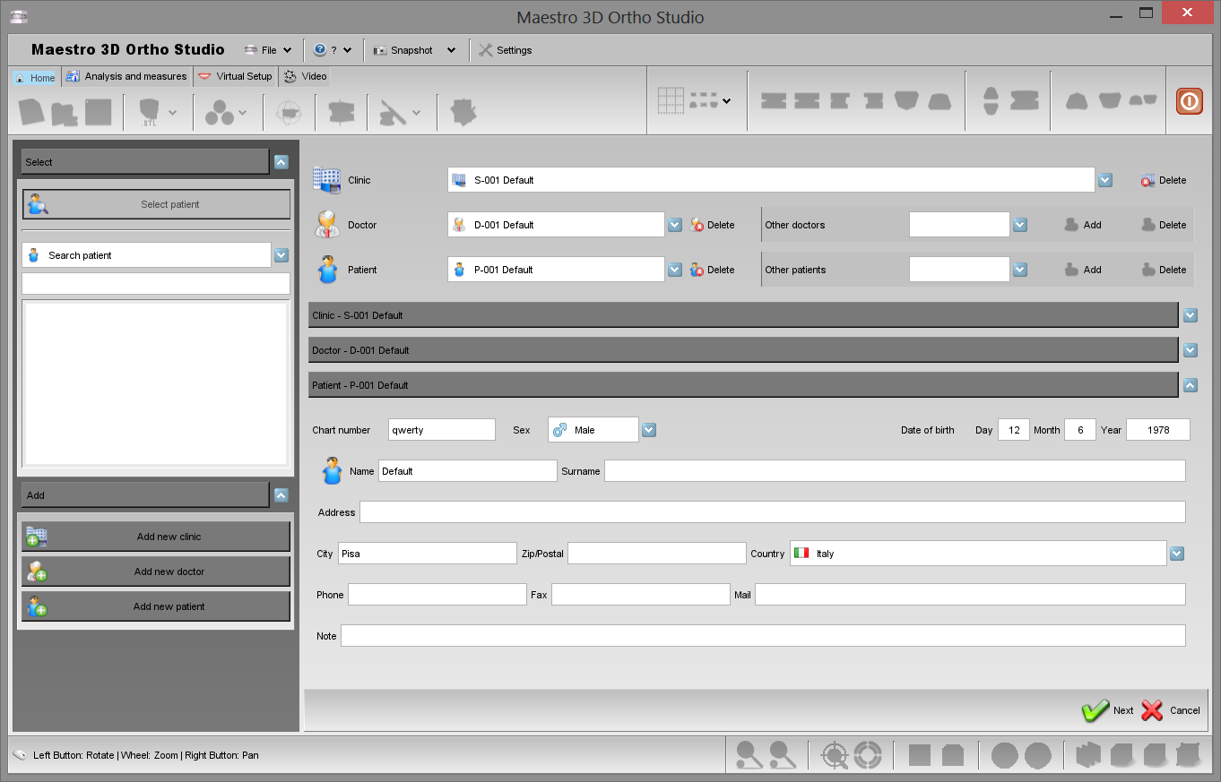
In the main side of the screen now it is possible to make the relationship between Surgery, Doctor and Patient. The first half of the main screen area allows to make the relationships between Surgery, Doctor and Patient (see picture below).
Select the surgery from combobox. The ![]() Delete button allows to delete the surgery currently selected. Please note that when pressing the Delete button the Surgery definition is phisically removed from the Database of the Surgeries.
Delete button allows to delete the surgery currently selected. Please note that when pressing the Delete button the Surgery definition is phisically removed from the Database of the Surgeries.
When the list of the Doctors associated to a given Surgery is empty and in general when it is necessary to add a new Doctor to the Surgery previously selected, it is possible to select a Doctor in Other doctors combobox and then pressing the ![]() Add button. The
Add button. The ![]() Delete button located nearby to the Other doctors combobox allows to remove the definition of a Doctor from the Database of Doctors.
Delete button located nearby to the Other doctors combobox allows to remove the definition of a Doctor from the Database of Doctors.
Select a Doctor from combobox. This allows to select one of the Doctors associated to the Surgery. The ![]() Delete button located nearby to the Doctor section allows to remove a Doctor from the Doctors of a Surgery without deleting the doctor from the Database of Doctors.
Delete button located nearby to the Doctor section allows to remove a Doctor from the Doctors of a Surgery without deleting the doctor from the Database of Doctors.
When the list of the Patients associated to a given Doctor is empty and in general when it is necessary to add a new Patient to the Doctor, it is possible to select a Patient in Other patients combobox and then press the ![]() Add button. The
Add button. The ![]() Delete button located nearby to the Other patients combobox allows to remove the definition of a Patient from the Database of Patients.
Delete button located nearby to the Other patients combobox allows to remove the definition of a Patient from the Database of Patients.
Select one of the Patients associated to the Doctor. The ![]() Delete button located nearby to the Patient section allows to remove a Patient from the Patients of a Doctor without deleting the patient by the Database of Patients.
Delete button located nearby to the Patient section allows to remove a Patient from the Patients of a Doctor without deleting the patient by the Database of Patients.
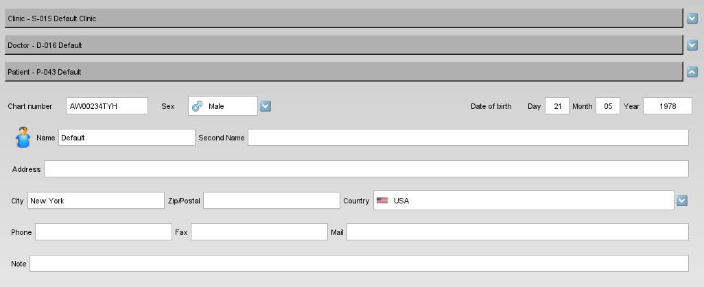
Please note that in the second half of the screen main area it is possible to modify the fields of the Surgery, Doctor and Patient previously added.
Pressing the ![]() Next button located in the lower right corner of the window allows to proceed in the definition of the case.
Next button located in the lower right corner of the window allows to proceed in the definition of the case.
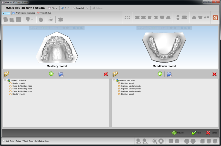
The task of choosing maxillary and mandibular models can be accomplished in three distinct way, see the image below.
- choosing a model by the tree of the Maestro Data (this is the folder in which the models acquired by Maestro 3D Dental Scanner are placed by default).
-
 importing a model by an external folder using the Open files from disk button (the allowed format for the models to import is the STL file format).
-
 importing a model by an external folder using the Import Ortho files from disk button (the allowed format for the models to import is the ortho file format).
-
 start the acquisition with Maestro 3D Dental Scanner.
Open an Existing Case
To open an existing case click on the ![]() Open case button located in the main toolbar.
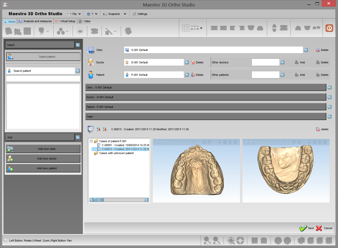
In the treeview it is now possible to select an existing case. To see all the cases of a given patient press the
Open case button located in the main toolbar.
In the treeview it is now possible to select an existing case. To see all the cases of a given patient press the ![]() Select patient button located in the left side of the screen.
Select patient button located in the left side of the screen.
In this phase it is possible to change the properties of a case, changing the Surgery, Doctor and Patient info and adding a new Surgery, Doctor and Patient. Also note that it is possible to move an unknown case or a case of a given Patient in a case of another Patient simply locating the case in tree and dragging it from the starting folder to the destination folder.
Pressing the ![]() Next button located in the lower right corner of the window it is possible to
proceed with the next operation.
Pressing the
Next button located in the lower right corner of the window it is possible to
proceed with the next operation.
Pressing the ![]() Cancel button break the process of opening an existing case.
Cancel button break the process of opening an existing case.
The image below shows the process of opening an existing case.
Changing the Local Origo
In order to change the Local Origo for the maxillary and mandibular models, press the ![]() Change Local Origo - Initial position button.
Change Local Origo - Initial position button.
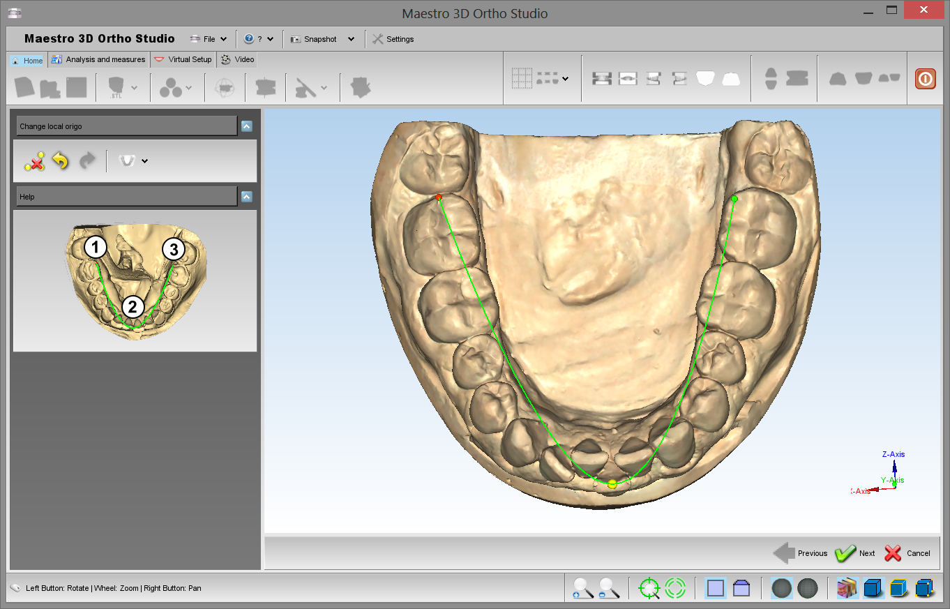
Double click over the model to add a spline as show in the image below in order to make an initial position of the local origo of the models.
Press Next or ![]() Change Local Origo - Precise position to go to the second step.
Change Local Origo - Precise position to go to the second step.
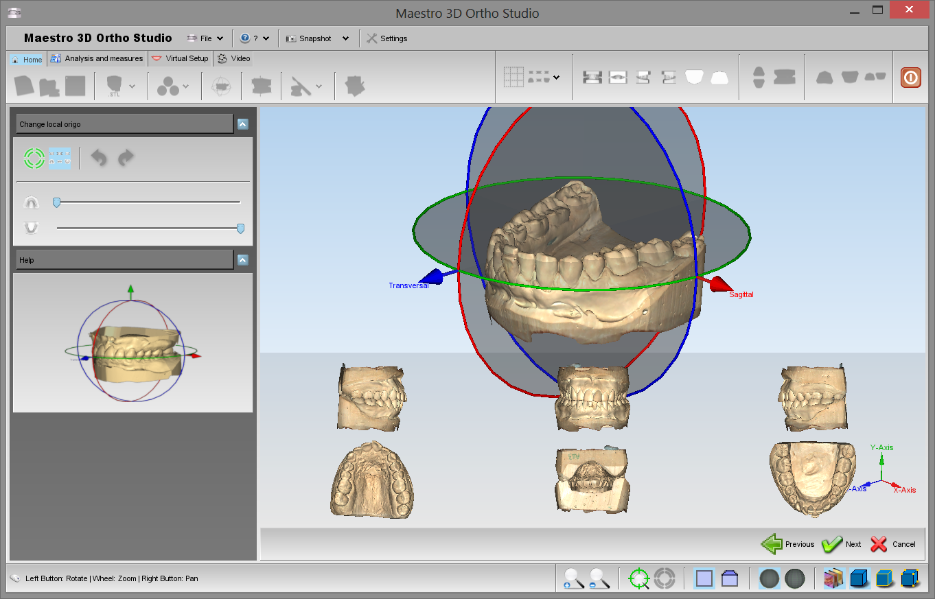
In the editing area appears a Manipulator (see image below). The center of the manipulator represents the origin of the coordinate system, the red arrow represents the X axis, the green arrow represents the Y axis and blue arrow represents the Z axis of the coordinate system. Using the Left mouse button it is possible to translate the Manipulator (dragging the arrows) or rotate the manipulator (dragging the circles). These operations allows to change the coordinate system of the models. Pressing the [[image:next.png] Next button located in the lower right corner of the editing area allows to move the maxillary and mandibular models in the new reference coordinate system. In order to apply the changes to the models, please remember to press ![]() the Save case button located in the main toolbar.
the Save case button located in the main toolbar.
Virtual Base Creation
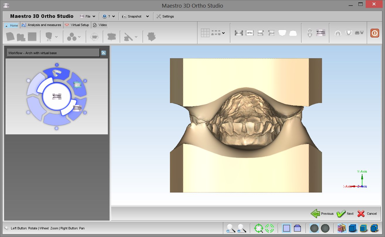
In order to add the virtual base for the maxillary and mandibular models, press ![]() the Add virtual base button.
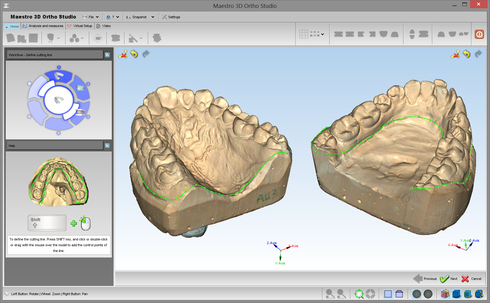
First step to perform when doing virtual base editing, it's to define a trimming line in order to remove the unimportant areas of model.
It's possible to define trimming line simultaneusly for both models. After defining trimming line, software automatically detect area to remove.
the Add virtual base button.
First step to perform when doing virtual base editing, it's to define a trimming line in order to remove the unimportant areas of model.
It's possible to define trimming line simultaneusly for both models. After defining trimming line, software automatically detect area to remove.
|
TIPS: SHIFT + click or drag with left mouse button to add a point of the spline. |
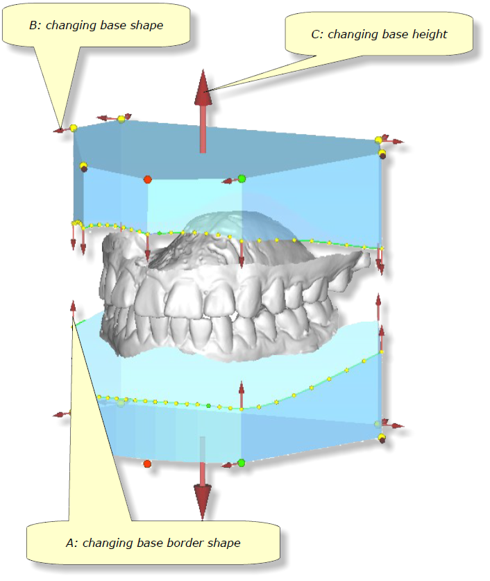
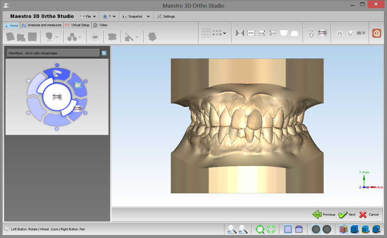
The second step is the editing operations on virtual bases. It's possible to choose several base types, in particular it's possible to choose between ABO, Parallel, Tweed and Ricketts models. It's also possible to perform simultaneusly several several editing operations for virtual base:
A: changing base border shape:
dragging points located at base border it's possible to change the shape of the
border itself. It's also possible to add/remove points using shift + left mouse double
click. It's also possible to draw the base border just using the shift + left mouse
button dragging near to the base border. Dragging the arrows located at base
border it's possible to move the border up and down.
B: changing base shape:
dragging points and arrows located at corners of virtual base it's possible to change the shape of the virtual base (for example it's possible to change the width and the length of bases). During all the editing operations, constraints that exists between angles/sides of base are preserved.
C: changing base height:
dragging the arrow positioned at base bottom it's possible to change the height of bases (this option it's disabled for ABO bases).
All operations concerning virtual base editing process are performed with Shift + left mouse button dragging (Shift + left mouse double click to add remove points to base border). Using the “Symmetrical changes” checkbox, editing will be performed simultaneusly on
both bases.
After finishing editing process just press Next button in order to finalize the editing procedure and merge the defined bases with maxillary and mandibular models.
|
TIPS: SHIFT + double-click / drag with left mouse button to add/remove points to base border. |
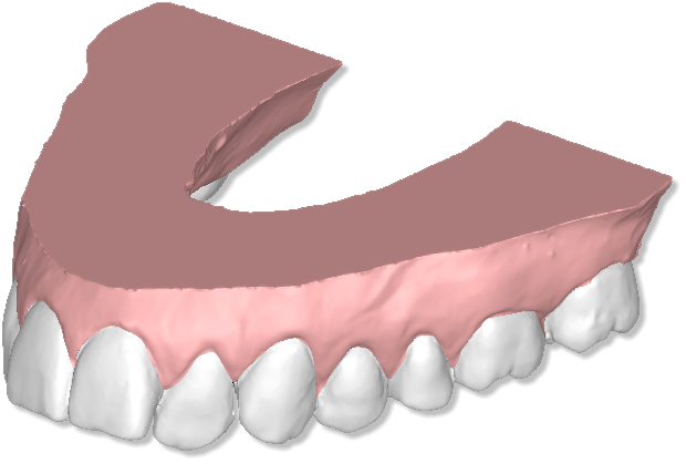
Stitching between base and model it's more smooth and the transition between arch and base it's smoother.
Sculpting
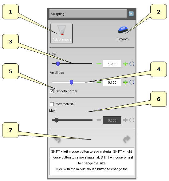
In order to make some modifications of the models, press ![]() the Sculpting button.
It's possible to add\remove material or smooth model surface by deciding the amplitude and speed of changes using the available sliders.
the Sculpting button.
It's possible to add\remove material or smooth model surface by deciding the amplitude and speed of changes using the available sliders.
- 1) add\remove material.
- 2) smooth surface.
- 3) size of the tool.
- 4) amplitude of the tool.
- 5) smooth the border of the tool area.
- 6) max material to add.
- 7) undo\redo.
|
TIP: SHIFT + wheel to change the tool size. |
Analysis and Measures
Occlusion Inspection
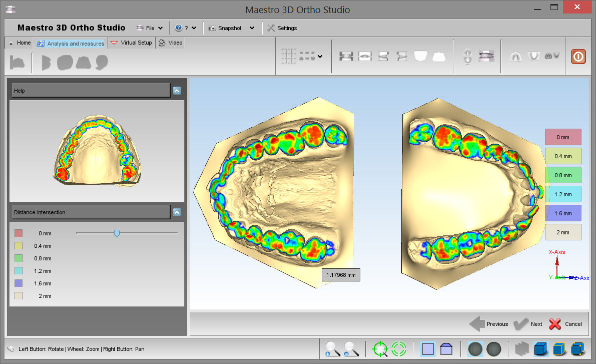
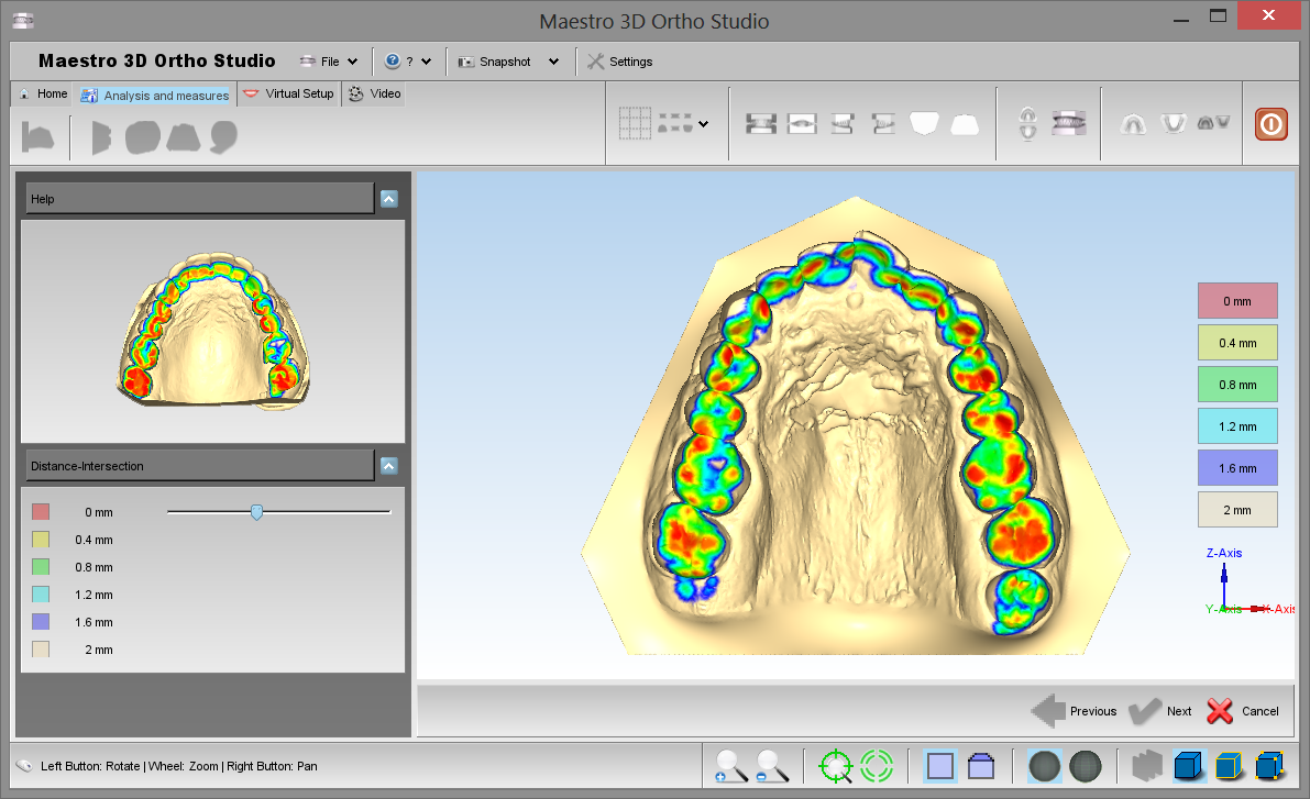
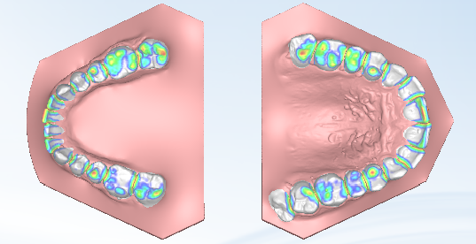
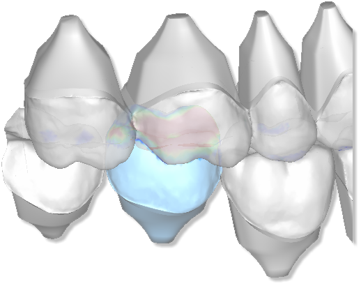
To see and analyze the occlusion inspection between maxillary and mandibular arcs just press the ![]() Occlusion inspection button. After the computation each point of the surface of an arch is painted with a color representing the distance by the opposite arch surface.
In the right side of the editing area is located a legend that explain the meaning of the colors.
It is also possible double clicking on the model to know the exact distance value for this point.
Please note that it is possible query for the value only for an area of the model with a color assigned.
Occlusion inspection button. After the computation each point of the surface of an arch is painted with a color representing the distance by the opposite arch surface.
In the right side of the editing area is located a legend that explain the meaning of the colors.
It is also possible double clicking on the model to know the exact distance value for this point.
Please note that it is possible query for the value only for an area of the model with a color assigned.
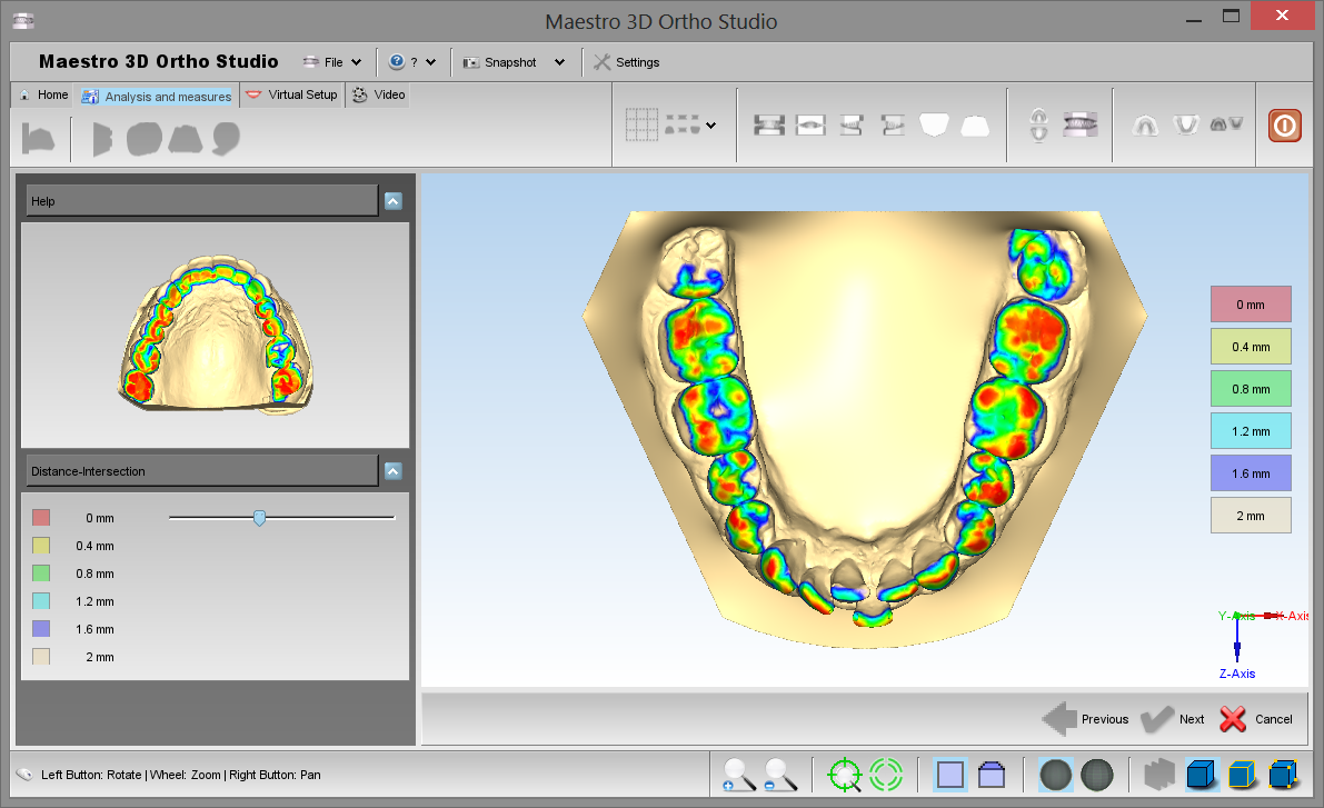
The following images shows the occlusion inspection visualized on both the arcs. To activate this visualization press the ![]() Open mouth button.
Open mouth button.
The following image shows the occlusion inspection visualized on the maxillary arch. To activate this visualization press the ![]() Show Maxillary button.
Show Maxillary button.
The following image shows the occlusion inspection visualize on the maxillary arch. To activate this visualization press the ![]() Show Mandibular button.
Show Mandibular button.
Cross Section
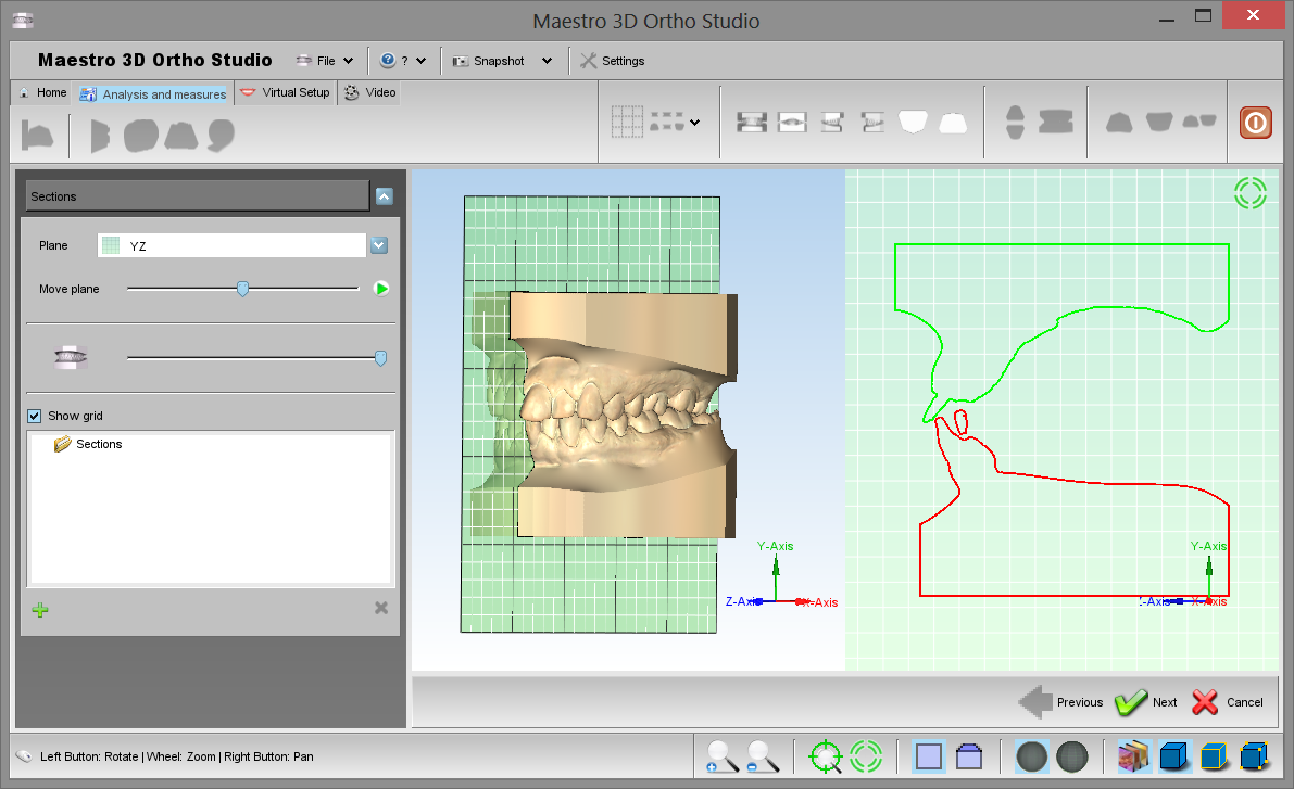
In order to perform the analisys of a cross sections, press the ![]() Sections button. 2D measurements over cross sections aligned to main axes.
It's possible to slide the sections and measure distances on 2D cross sections.
With the left toolbox it's possible to change the plane, change the transparency of the model and see the animation.
See the image below:
Sections button. 2D measurements over cross sections aligned to main axes.
It's possible to slide the sections and measure distances on 2D cross sections.
With the left toolbox it's possible to change the plane, change the transparency of the model and see the animation.
See the image below:
|
TIPS: double-click with left mouse button to add a point into 2D grid. |
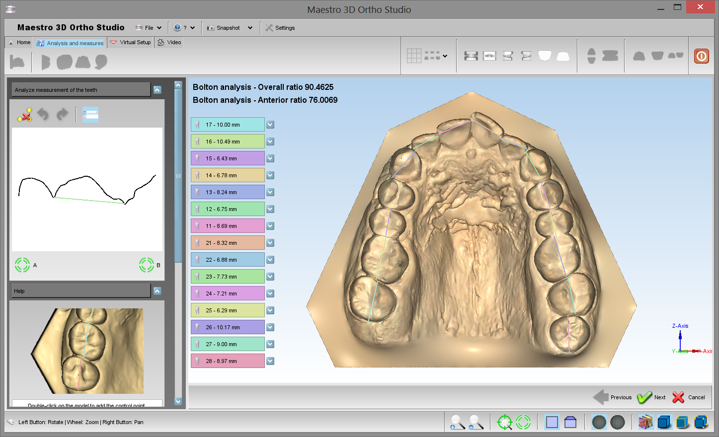
Teeth Measures
In order to perform the analisys of the distances between theeth, select the arch to inspect using the ![]() Show Maxillary button button or the
Show Maxillary button button or the ![]() Show Mandibular button and then press the
Show Mandibular button and then press the ![]() measures button.
measures button.
The image shows the process of measuring distances between theeth in the maxillary model. As for the process of the cutting line definition, it is possible to add, remove or modify the position of the points.
For each line segment defined by two consecutive points the current length of the segment is showed.
On the left side of the screen the total length and the average length of the segments are showed too.
Using the ![]() Undo button and the
Undo button and the ![]() Redo button it is possible Undo / Redo all the operations performed.
It is also possible to clear the measure using the
Redo button it is possible Undo / Redo all the operations performed.
It is also possible to clear the measure using the ![]() Reset button.
In order to save the measures, after pressing the [[image:Next.png] Next button, please remember to press the
Reset button.
In order to save the measures, after pressing the [[image:Next.png] Next button, please remember to press the ![]() Save case button located in the main toolbar.
Save case button located in the main toolbar.
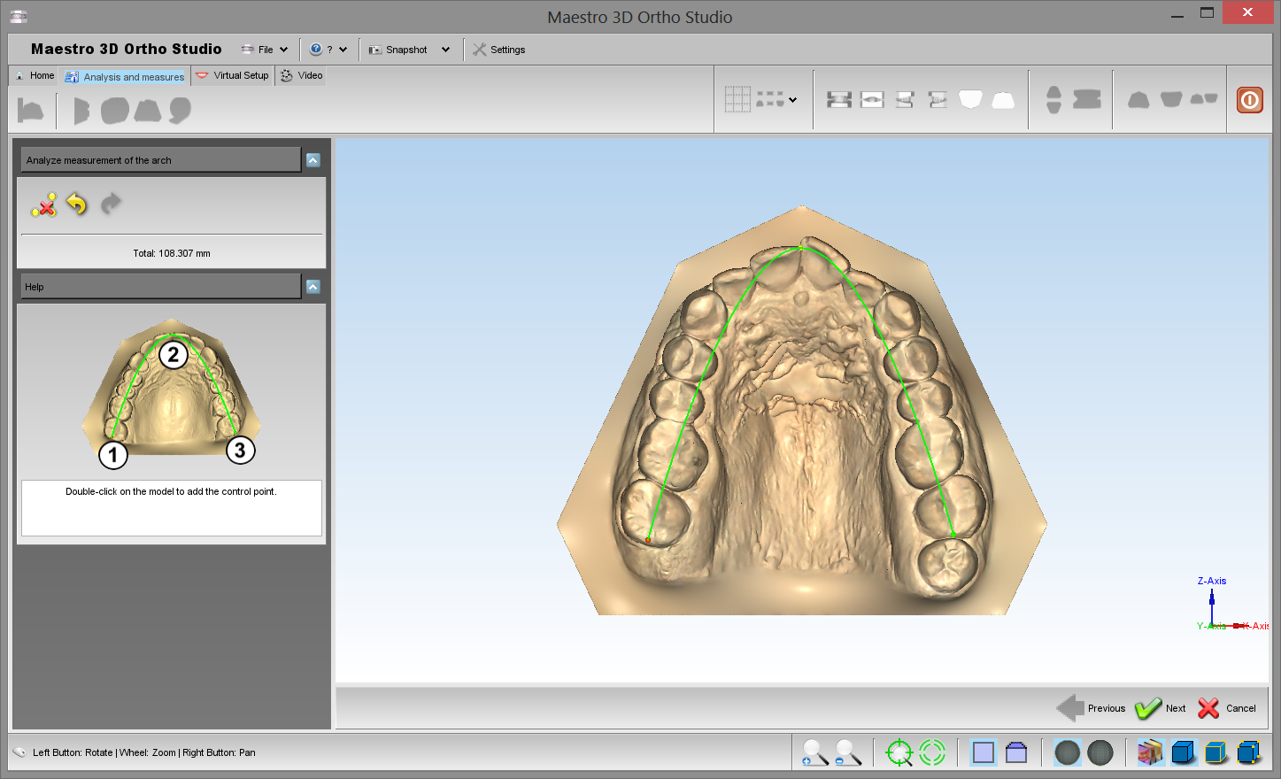
Arch Length
In order to perform the analisys of the arch length, select the arch to inspect using the ![]() Show Maxillary button button or the
Show Maxillary button button or the ![]() Show Mandibular button and then press the
Show Mandibular button and then press the
![]() measures button.
measures button.
|
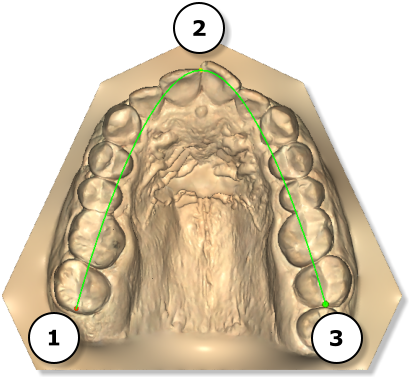
TIPS: double-click with left mouse button to add a point of the spline to compute the arch length. |
Put the points in the following order to define a correct spline. It's possible to add more than 3 points.
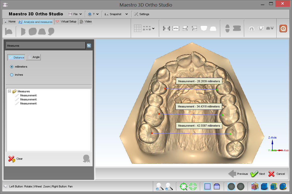
Free Measures
In order to perform the measures of length or angles, select the arch to inspect using the ![]() Show Maxillary button button or the
Show Maxillary button button or the ![]() Show Mandibular button and then press the
Show Mandibular button and then press the ![]() measures button.
measures button.
|
TIPS: double-click with left mouse button to add a point. |
Virtual Setup
With this feature, you can make a setup of both jaws and create all the models needed to complete the treatment. It's possible to add the custom attachments, brackets and the label 3D.
Tooth Segmentation
Detect Margin
In order to perform the tooth segmentation, select the arch to segment using the ![]() Show Maxillary button or the
Show Maxillary button or the ![]() Show Mandibular button and then press the
Show Mandibular button and then press the ![]() Tooth Segmentation button. Before this it's necessary complete the measurement of individual teeth.
Tooth Segmentation button. Before this it's necessary complete the measurement of individual teeth.
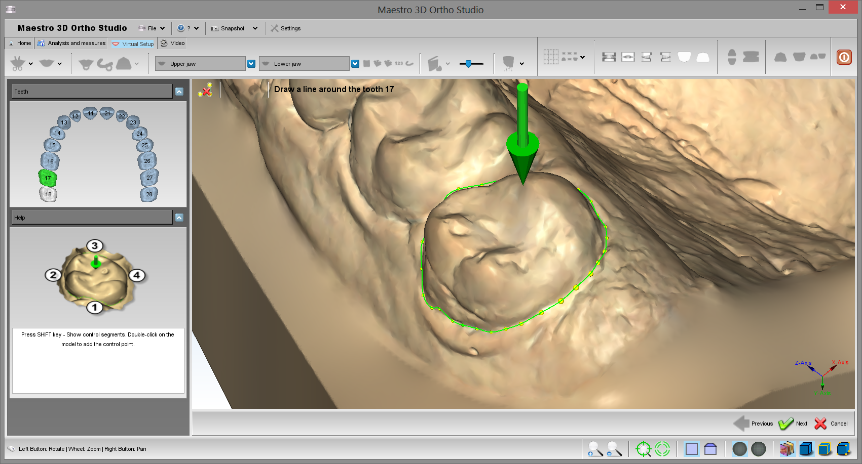
The first step is identify the margin of the tooth. See the image below.
To identify the margin of the tooth, double-click with the mouse near the margin to add a new control point as showed below:
Every two points entered by the user, the software makes a line near on the margin of the tooth. Usually is enough 4 clicks to draw a margin, as shown in figure. If the autocomplition of the line is not correct, press CTRL + Z or press ![]() button and try to add a new click in a different position example closer to the previous point.
button and try to add a new click in a different position example closer to the previous point.
|
TIPS:
|
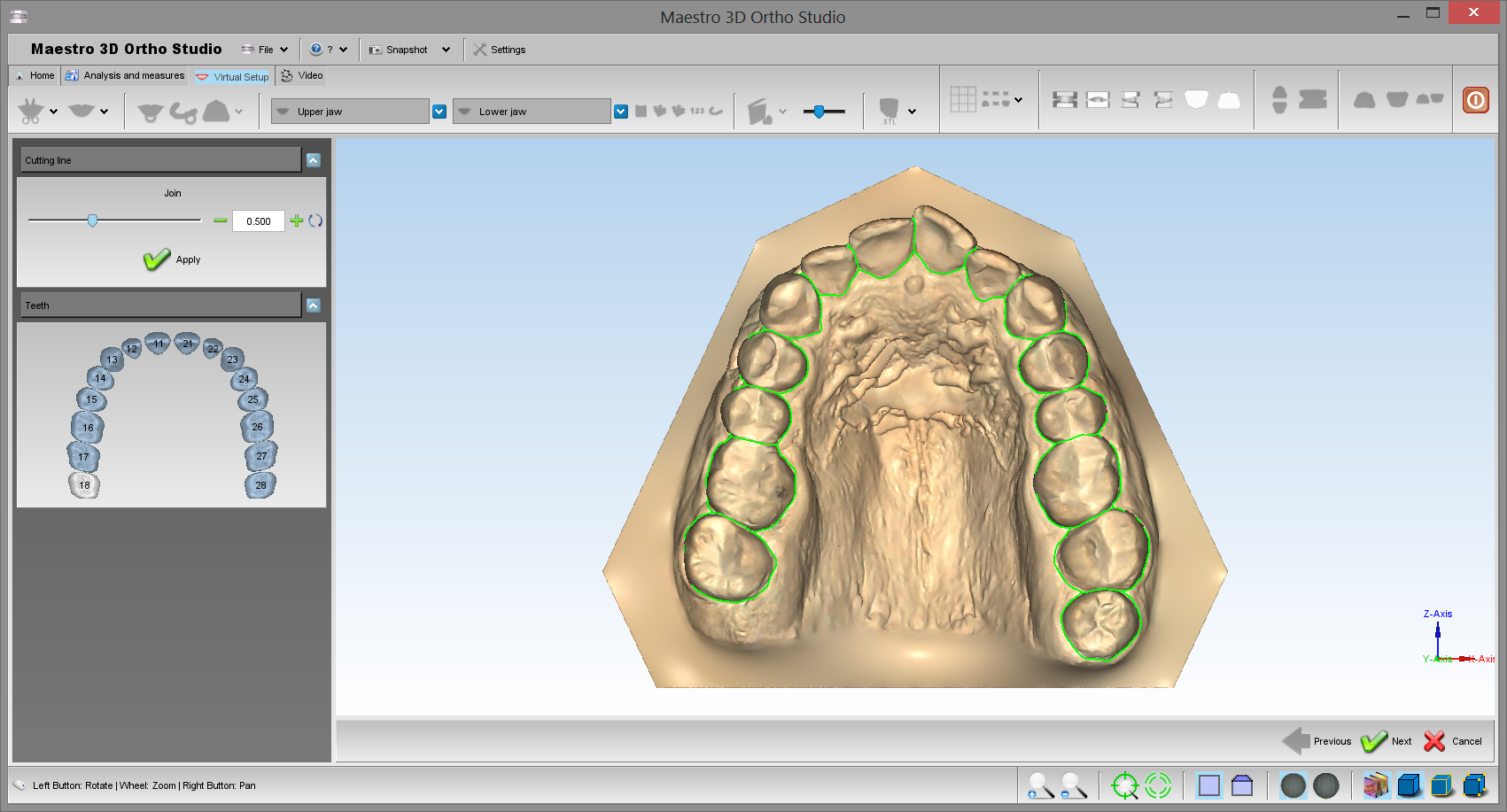
Cutting Line
In order to carry out the cutting line of the tooth segmentation, select the arch where you want to work, by using the ![]() Show Maxillary button or the
Show Maxillary button or the ![]() Show Mandibular button and then press the
Show Mandibular button and then press the ![]() Cutting line button. Before this, it is necessary to complete the previous step of Detec Margin.
See the image below:
Cutting line button. Before this, it is necessary to complete the previous step of Detec Margin.
See the image below:
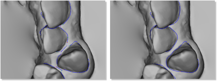
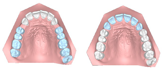
The value Join shows the distance where the teeth's single cutting lines are joined. On the image below, you can see an example that shows the result by applying a value of 1.0 mm (image on the left) and a value of 0.5 mm (image on the right).
|
TIPS:
|
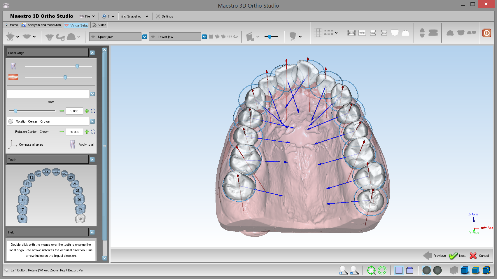
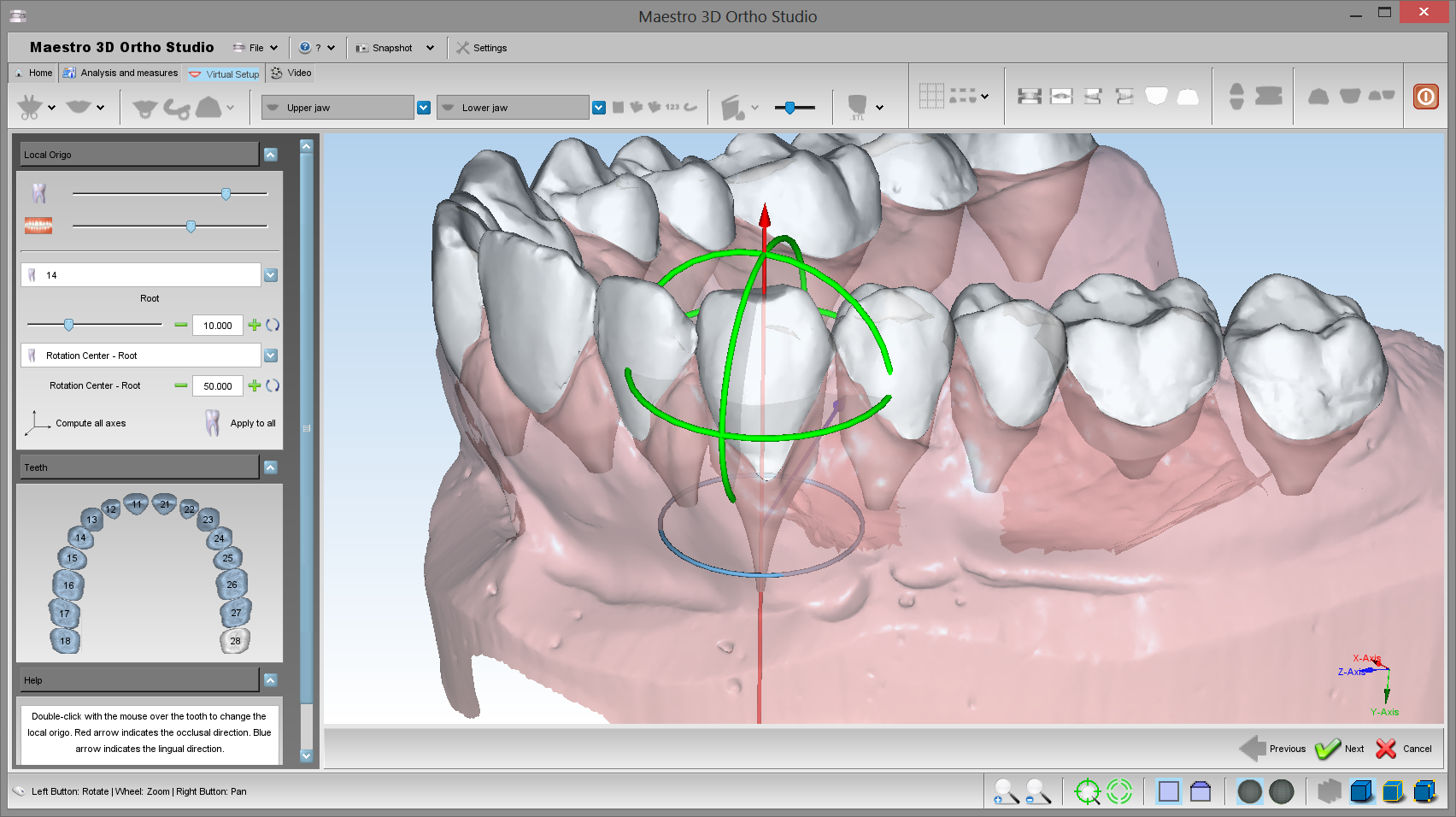
Tooth Local Origo
In order to perform the local origo of each tooth, select the arch to segment using the ![]() Show Maxillary button or the
Show Maxillary button or the ![]() Show Mandibular button and then press the
Show Mandibular button and then press the ![]() Change local origo button. Before this it's necessary complete the previous step of Cutting Line.
See the image below:
Change local origo button. Before this it's necessary complete the previous step of Cutting Line.
See the image below:
To change the local origo of a tooth, double click over the tooth and use the manipulator to change the origo. When you change the local origo the virtual root of the tooth change direction. Use the left toolbox to change the root dimension when a tooth is selected.
See the image below:
|
TIPS: click with center mouse button to change the rotation center of the trackball. |
Virtual Setup
In order to perform the virtual setup, press ![]() the Virtual Setup button.
the Virtual Setup button.
In this step you can translate and rotate the teeth in order to obtain the desired final position. To select a tooth, click with left mouse button over a tooth.
|
TIPS: SHIFT + left mouse button to translate the teeth selected. CTRL + left mouse button to rotate. Click with the middle mouse button to change the center of rotation of the trackball. |
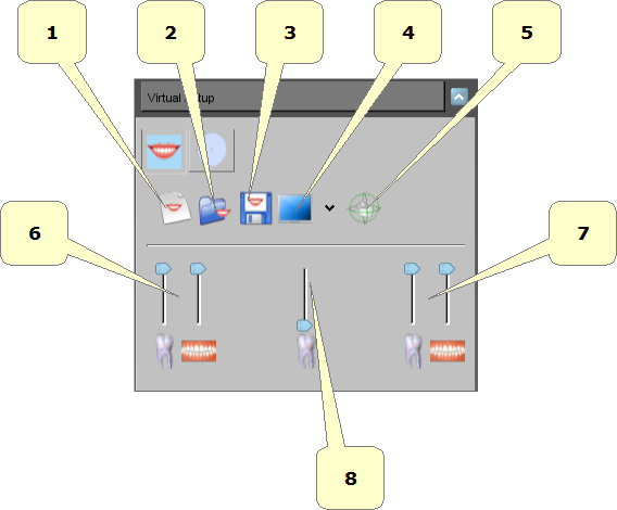
Take a look to the GUI on the left of the screen that allows to access to all the functionalities of the Virtual Setup.
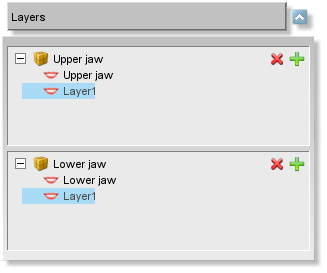
Layers
The layers are the steps that are useful to work with some groups of teeth in different period, i.e.:
you can move the posterior teeth and build a layer1.
than you can move the anterior teeth and build a layer2.
In this way when the software builds a set of virtual models, it is obtained:
| Original model | |
| virtual model (1) | Clear aligner 1 |
| virtual model (2) | Clear aligner 2 |
| ... | ... |
| Layer1 | Clear aligner L1 |
| virtual model (k) | Clear aligner k |
| virtual model (k+1) | Clear aligner k+1 |
| Layer2 | Clear aligner L2 |
So the first set of aligners don't move all teeth but only the posterior teeth. Only after some weeks, when you start to the layer1 you are ready to move the the anterior teeth.
It's possible to work only with the last layer. If you select a different layer, all
functionalities will be disabled.
Main toolbox
- 1) start a new setup project.
- 2) open an existing setup project.
- 3) exports the current setup project.
- 4) split the screen.
- 5) show/hide tooth manipulator.
- 6) show animation.
- 7) change teeth/gum transparency.
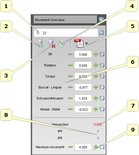
Movement Overview
With this toolbox it's possible to select a tooth from the combo menu and access to all operations of the single tooth.
- 1) list of all teeth.
- 2) reset the position of the selected tooth.
- 3) extract and restore the selected tooth.
- 4) movements in the canonical directions of the selected tooth. The rotations are expressed in degrees and translations in millimeters.
- 5) this value is the maximum movement of the selected tooth. The tooth that exceeds this value is colored red. It's just a visible warning.
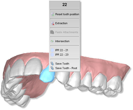
IPR - Interproximal reduction
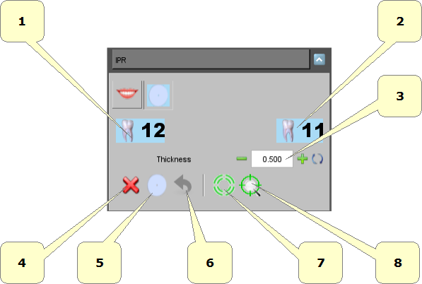
Interproximal reduction (IPR), also known as tooth stripping, is used when teeth are overcrowded and involves the dentist stripping away a portion tooth in order to create space. During setup phase, it's possible active the IPR pressing with right mouse button over a given tooth. A popup will appear and can be choose to do IPR with neighbour teeth.
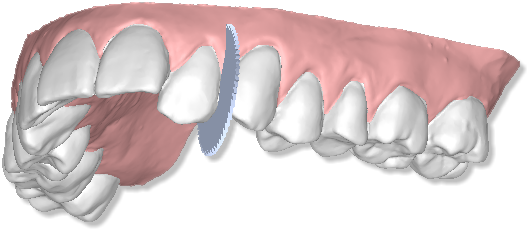
A blade will appears in between selected teeth.
At this point in the section related to the IPR in the left of the screen can be select the amount of IPR to perform, it's possible apply the IPR pressing the button ![]() .
.
- 1) cancel or press ESC.
- 2) compute IPR.
- 3) undo.
- 4) IPR amount.
Consider that it must apply IPR at beginning of each layer. Consider that IPR cutting plane it's computed automatically. Please also consider that if choosing to do 1 mm of IPR between two teeth, for example between 22-23, 0.5 mm are applied to a 22 and 0.5 mm to 23.
See the example of the final result after IPR procedure.
Ideal Arch
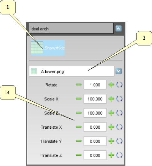
With this toolbox it's possible to show an ideal arch in the editing area. This can be used as a visual guide to move the teeth.
- 1) show/hide the ideal arch.
- 2) list of available ideal arch. To add a new arch:
- add new images as png file 32 bit with alpha channel (if you want to use the trasparency) into the subfolder idealarch under the ortho studio installation folder.
- 3) rotate, scale and translate the ideal arch to find the correct position.
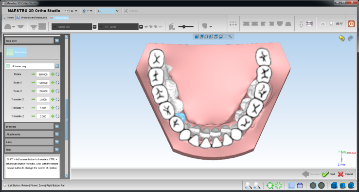
Below an example of an ideal arch.
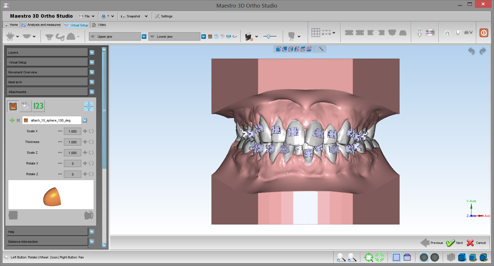
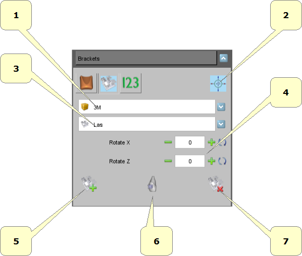
Brackets Module
With this toolbox it's possible to add the brackets over the teeth.
- 1) list of available brackets brand.
- 2) list of available brackets type for the selected brand.
- 3) add a new bracket. Hold SHIFT and double-click with the mouse over the tooth to add it.
- 4) remove the selected bracket.
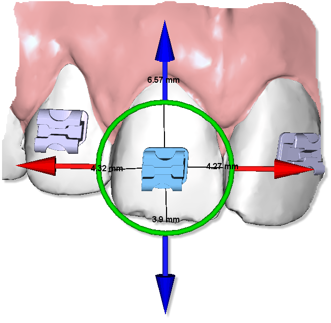
Below, there is an example of a bracket with manipulator.
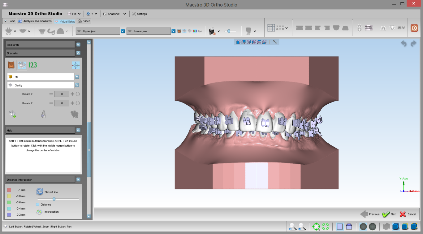
Another example of a case with all brackets.
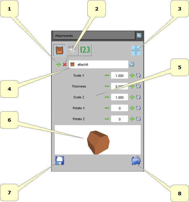
Attachments
- 1) add a new attach. Hold SHIFT and double-click with the mouse over the tooth to add it.
- 2) remove the selected attach.
- 3) list of available attachments.
- 4) thickness of the attachment.
Below, there is an example of an attachment with manipulator.
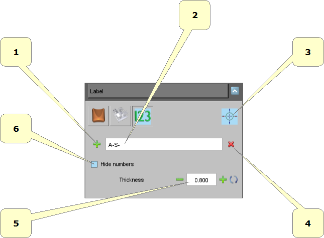
Label
It's possible to put a 3D text over the gum or over the teeth. It's useful to identify the models after printed.
- 1) add a new label. Hold SHIFT and double-click with the mouse over the gum or over the teeth.
- 2) prefix of the label, i.e.: initials of the patient's name.
- 3) remove the selected label.
- 4) thickness of the label.
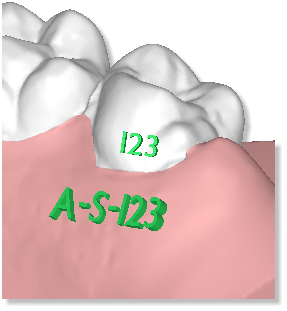
Below an example of two labels over the model.
The written 123 will be replaced with the correct numeration after the build of the virtual models.
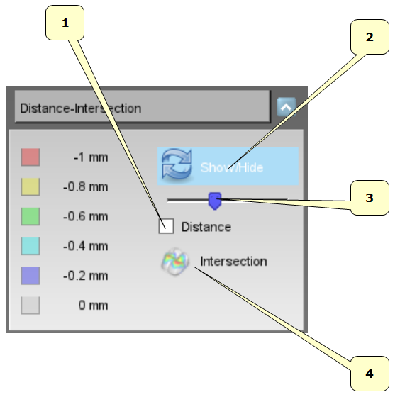
Show intersection/distance
- 1) teeth distnce.
- 2) show/hide color map over the teeth.
- 3) scale of the measures.
- 4) computer intersections.
Below an example of visualization of teeth distance.
Below an example of visualization of teeth intersections.
Please note that it's necessary to recompute intersections any time you make a change. It's possible also recompute the intersections for a single tooth just pressing right mouse button over a given tooth and selecting the intersection button in the popup menu.
Teeth information
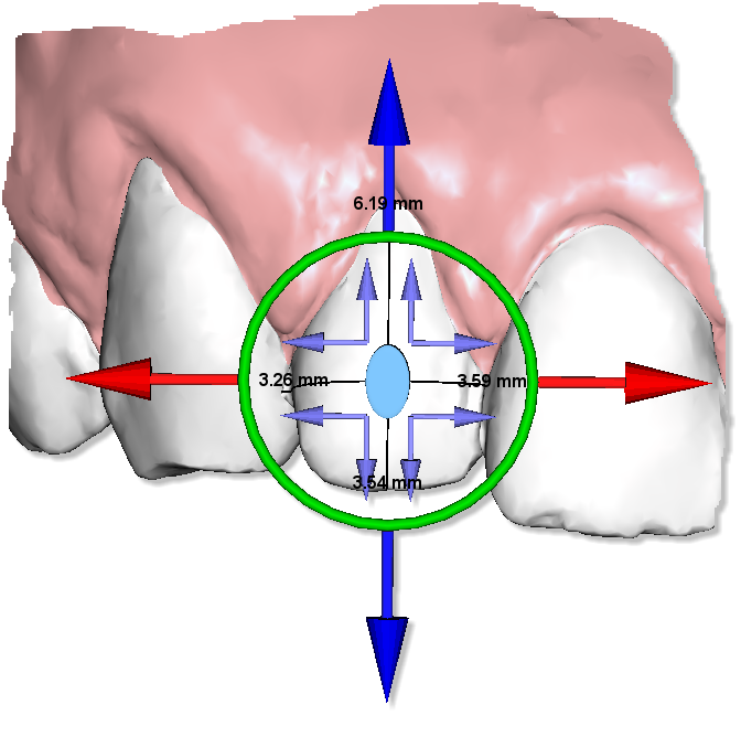
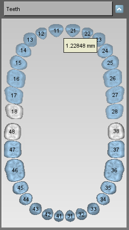
Move the mouse over a tooth, it shows an informative label about the tooth's movement, see the image below.
Models Builder
In order to perform the models builder, select the arch using the ![]() Show Maxillary button or the
Show Maxillary button or the ![]() Show Mandibular button and then press the
Show Mandibular button and then press the ![]() Models builder button.
Models builder button.
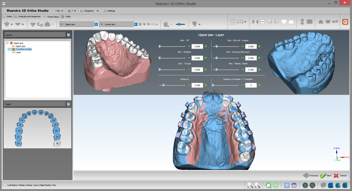
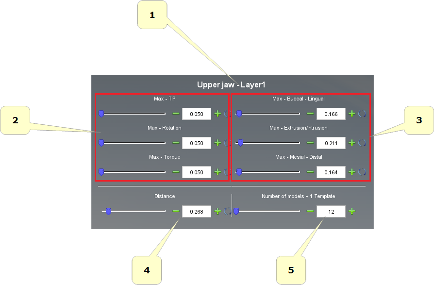
In the left of the screen there is a treeview with all layers. Between two layers there is a transition models item. Select it to choose the movement of the teeth for each virtual model. Belown an example of the models builder function:
in detail:
- 1) start and end position, from layer(n) to layer(n+1). In this example: from Upper Jaw to Layer.
- 2) information about distance:
- Average: is the average value of the movement of all teeth.
- Max: is the value of the max movement between all teeth.
- 3) desidered value of the max movement of the teeth for each virtual model.
- 4) number of virtual models that will be generated.
- 5) real value of the max movement of the teeth for each virtual model.
- 6) this label indicates that there will be generated a template model to stick attachments/brackets.
Cut and Close
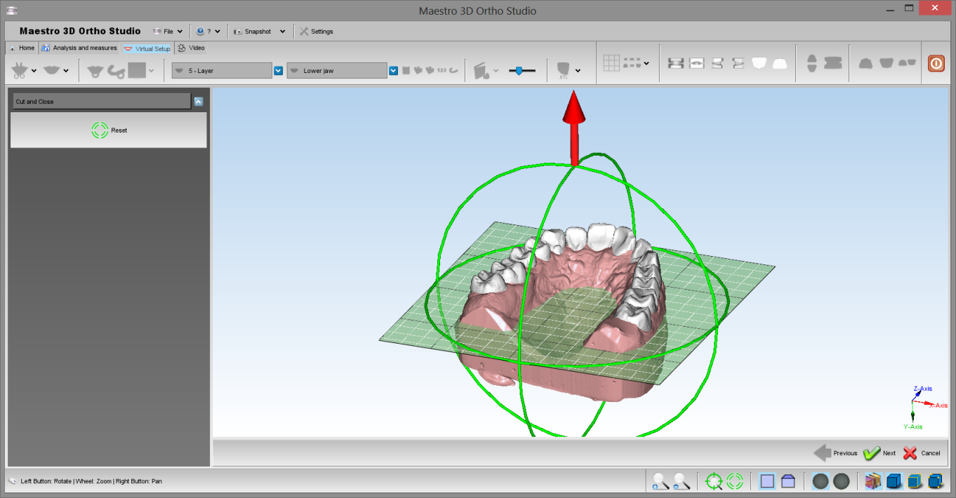
This feature was created to remove from virtual models all surface that it's not necessary for the construction of invisible aligners. This saves a lot of print material.
In order to perform the cut and close, select the arch using the ![]() Show Maxillary button or the
Show Maxillary button or the ![]() Show Mandibular button and then press the
Show Mandibular button and then press the ![]() Cut and Close button.
Cut and Close button.
Rotate the plane with the green circles and translate the plane with the red arrows. Press the ![]() Next button to cut and close all virtual models.
Next button to cut and close all virtual models.
Request the Viewer's License
The viewer is a tool which offers to doctors the possibility to see and check over digitals model and virtual setup.
It is possible to download the software from the following pages as shown in the red box of the picture below: www.age-solutions.com/sw.asp
After the software installation, as shown in the section Software_Installation, remember to set up correctly the UAC User Account Control and the Administrator's Rights
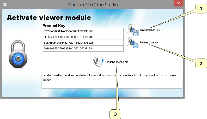
After the first execution, the software will show a window, like the one below:
- 1 - Press the button Save product key to save the file with the serial code of the product on the desktop.
- 2 - Press the button Request license to open web pages to ask for the license about the use of the software, otherwise, make the access through this link.
- 3 - Press the button Load license file... to charge the license file received by email after the registration procedure, described below.
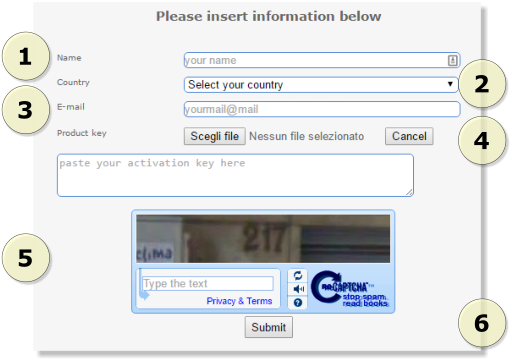
From point 2 you have access on the page where you request the license, as shown in the picture below: (we suggest to use Google Chrome or Mozilla Firefox browser or even Microsoft Internet Explorer browser but on "Compatibility View" modality).
- 1 - Insert your name
- 2 - Insert your country
- 3 - Insert the email address where the license for the use of the software will be sent
- 4 - Press the button Browse to charge the product key saved before on the desktop.
- 5 - Insert the security code
- 6 - Press the button Submit
You will receive the license file by email after a few time. Data information are used only to statistical aim and they will not spread to other companies in no way.
Maestro 3D iPad Viewer
Procedures for downloading an orthoipad file for viewing
Tap the ‘Files’ button on the main menu at the bottom of the screen. Then tap the button at the bottom of the form labeled “FTP Import”. The following form will display. The three input fields (Address, Username and Password) will be empty on first use.
